
Cellular signal repeaters are specified by three linked numbers: frequency band, gain in dB, and output power in dBm, with each +10 dB of gain equating to a tenfold rise in radiated output power and a much larger coverage footprint [S1].
The practical sizing job starts with the outdoor signal level at the donor antenna, the band(s) your carrier transmits on (LTE 700, PCS 1900, AWS 1700, LTE 2600, NR for 5G), and the construction of the building, since concrete, low-E glass, and foil-backed insulation each attenuate the uplink and downlink paths differently [S1][S3]. For an in-depth look at the same architecture choices on the WiFi side, see the WiFi signal repeater selection guide.
Frequency Bands and Carrier Compatibility
Cellular repeaters must be band-matched to the carriers serving the site, otherwise the amplified path carries no usable signal and the noise figure of the unit can degrade the uplink for nearby users on the same band [S1]. Common bands include GSM 900, DCS 1800, CDMA 850, CDMA 2000, WCDMA 2100, AWS 1700, LTE 700, LTE 2600, and PCS 1900; 5G NR is added as operators re-farm or layer new spectrum [S1]. Multi-carrier amplifiers that handle several bands simultaneously are preferred where multiple operators serve the building, because the repeater continues to work if a tenant switches carrier [S3].
Single-carrier amplifiers only boost the frequency blocks of one carrier, which gives slightly better selectivity but ties the asset to one operator; multi-carrier units trade a small amount of selectivity for tenant flexibility [S3]. For more on choosing industrial RF hardware across bands, the broader signal repeater reference page covers the related industrial repeater category used in SCADA and process-control telemetry.
Gain, Output Power, and the Coverage Equation
Home-class boosters typically deliver 50-70 dB of gain and 20-30 dBm of output power, while commercial and industrial units reach 70-100 dB and 30-50 dBm respectively, with the higher-output models needed to push signal through masonry, metal decks, and below-grade spaces [S1]. A 10 dB gain increase is equivalent to a tenfold increase in output power in coverage terms, which is why stepping from a 65 dB home unit to a 75 dB commercial unit is rarely a marginal upgrade [S1].
Coverage numbers cited by vendors are derived under a clean RF path and a strong outdoor donor signal; in practice, a unit rated for 5,000 sq ft with good outside signal may cover only 1,500-2,500 sq ft inside a steel-and-concrete structure [S3]. Lintratek's reference sizing note ties the same three parameters to area, with the practical rule that residential and small offices need low-to-medium gain units, while larger commercial floorplates require higher-gain, higher-power hardware [S1].
Antenna Separation, Isolation, and Oscillation Control
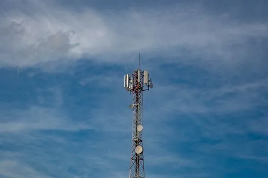
Donor and indoor antennas must be isolated by a minimum of roughly 20 ft vertical or 50 ft horizontal separation, with the larger number used when the indoor antenna radiates above the donor or when building reflections are strong [S3]. Insufficient isolation causes the amplifier to feedback into its own input, which the unit then interprets as a strong donor signal and reduces uplink gain, collapsing the very coverage it is supposed to deliver [S3].
Wilson Amplifiers' installation guidance also flags shielding and cross-band filtering as part of the same isolation problem: a multi-band amplifier with poor duplexer filters between uplink and downlink blocks will self-oscillate on the strongest band first, even when antenna geometry is correct [S3]. On industrial process-control sites with metal structures and cable trays, the practical isolation number is often 1.5-2x the residential minimum, so site survey work is non-negotiable.
Sizing by Coverage Area and Use Case
The three deployment tiers most buyers face map cleanly onto hardware: residential (one floor, under ~5,000 sq ft), small commercial (5,000-15,000 sq ft), and large commercial or active DAS (15,000 sq ft to 1M+ sq ft) [S2][S3]. The residential tier is served by 50-70 dB / 20-30 dBm units; small commercial by 70-80 dB / 27-33 dBm units; and large commercial by 80-100 dB / 33-40 dBm boosters feeding a coax or fiber DAS with multiple indoor antennas [S1][S2].
Vehicle-class repeaters are a separate duty: lower gain, lower power, omnidirectional donor antennas, and a single interior rebroadcast antenna sized to a cabin or bus body, not a building [S3]. For stationary industrial sites, the same repeater architecture appears in SCADA telemetry links where the industrial modem and DTU selection spec map covers the upstream side of the same radio chain.
Comparison: Home vs Small Commercial vs Large Commercial

Selection by duty can be reduced to four criteria: gain, output power, typical coverage, and donor-antenna count, and the three main classes line up as follows: residential boosters sit at 50-70 dB / 20-30 dBm / up to 5,000 sq ft / 1 donor antenna; small commercial units reach 70-80 dB / 27-33 dBm / 5,000-15,000 sq ft / 1-2 donor antennas; and large commercial or active DAS hardware delivers 80-100 dB / 33-40 dBm / 15,000 sq ft to 1M+ sq ft / multiple donor and indoor antennas [S1][S2][S3].
Buyers who only need in-vehicle coverage should not pick a home unit, because the 50-70 dB gain will over-drive a small cabin and oscillate without a strict 20 ft vertical separation that is physically impossible inside a car or van [S3]. Conversely, a buyer trying to cover a 50,000 sq ft warehouse with a 65 dB residential booster will see a 500-1,500 sq ft bubble of useful signal at best, because the 20-30 dBm output ceiling cannot overcome the path loss of the building fabric [S1][S3].
Limitations, Failure Modes, and Sourcing Standards
Repeater sizing fails most often in three ways: band mismatch with the serving carrier, donor-to-indoor antenna isolation below the 20 ft / 50 ft threshold, and overspecifying gain in a small space where the unit auto-attenuates and looks "broken" [S3]. Each of these is mechanical to diagnose with a site survey and a spectrum check, but each also voids the value of an otherwise correctly specified unit [S1][S3].
On the sourcing side, FCC Part 20 and the equivalent carrier-certification rules govern consumer boosters in the US, while CE and the relevant national regulators apply in Europe; buyers should confirm the exact band plan, not just the marketing "5G ready" label, before commissioning a system [S1][S3]. For a broader look at industrial RF systems that share the same gain / power / isolation tradeoffs, the signal repeater encyclopedia entry covers the related industrial-class hardware used outside the consumer cellular band.
Two signals worth tracking before purchase: a verified outdoor RSRP or RSSI reading at the planned donor location, and a written isolation measurement between donor and indoor antennas in the as-built geometry, both of which determine whether the chosen gain figure will actually deliver the rated coverage on site [S3].
Spec-level background on the components involved: linear guide, and crossed roller guide.