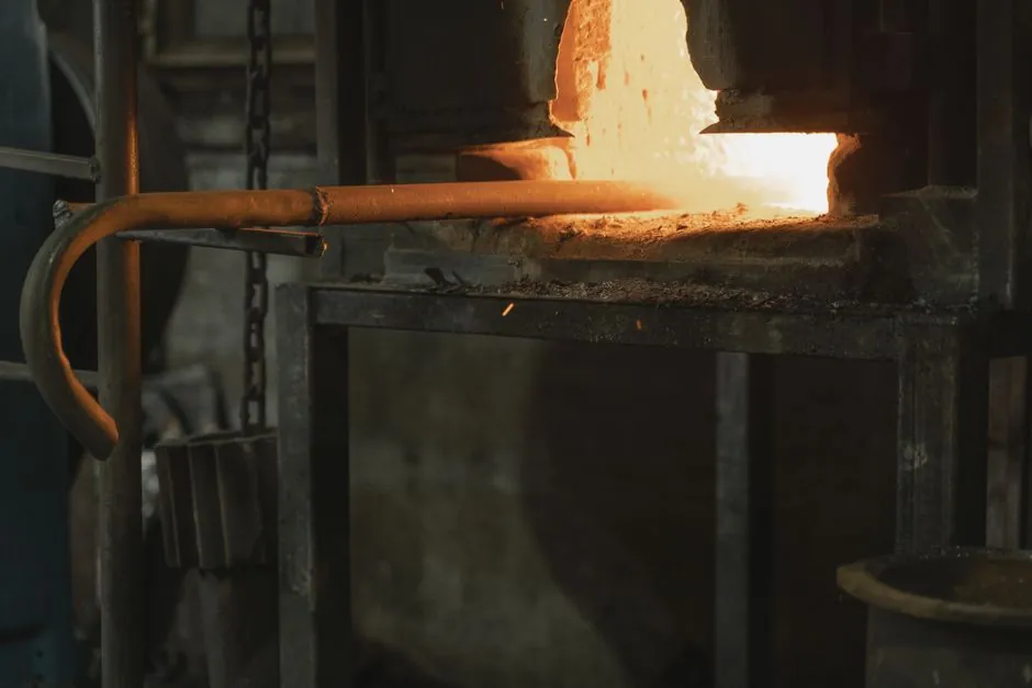
A cupola designed for a 10 t/h iron melting rate can use a 1,220 mm internal shell diameter when the metal-to-coke ratio is 8.1:1, with blower capacity set by the same duty calculation [S3].
Practical cupola envelopes extend from 450 to 2,000 mm internal diameter across approximately 1–30 t/h, so diameter is a first sizing variable rather than a universal conversion factor [S4].
Start with duty, fuel ratio and combustion mode
Published cupola sizing uses a combined relationship among melting rate, metal-to-coke ratio and furnace geometry: at 10 t/h and an 8.1:1 ratio, the specified internal diameter is 1,220 mm, equivalent to 48 in [S3]. That example is a defensible reference point, but it does not establish one shell size for every 10 t/h installation.
Cold-blast cupolas are associated with melting rates of roughly 2–10 t/h, while hot-blast operation burns carbon monoxide in a recuperator and heats the blast to about 400–600°C [S5]. Combustion mode changes the usable heat release, coke consumption, scrap tolerance and spout-temperature response, so it must be fixed before finalizing the cupola furnace shell diameter.
A practical sizing sequence is therefore: establish the required hot-metal output, select the metal-to-coke ratio, choose cold-blast or hot-blast operation, calculate the air and fuel demand, and then select the smallest shell that meets the duty without exceeding permissible gas velocity and charge residence requirements [S3][S5].
Reference points for diameter selection
The 1,220 mm internal-diameter design for 10 t/h at 8.1:1 metal-to-coke provides a direct reference point, while the broad published operating envelope covers internal diameters from 450 mm at the small end to 2,000 mm at the large end, with melt rates from approximately 1 to 30 t/h [S3][S4].
These points should be plotted on a log-log diameter-versus-output chart rather than joined by a single straight proportional line. Published data include a 500 kg/h design with shell diameters from 1 to 2 m, demonstrating that the same nominal output was not represented by one universal diameter [S2].
Compare shell geometry against four design criteria

For cold-blast versus hot-blast systems, the comparison is straightforward: cold blast serves roughly 2–10 t/h with about 60% furnace efficiency, while hot blast raises blast temperature to 400–600°C, improves economic efficiency, permits more scrap steel and delivers more consistent iron composition [S5].
On output, cold-blast equipment is suited to the lower portion of the furnace range, while hot blast is more appropriate where thermal recovery and chemistry control justify added complexity [S5]. On fuel consumption, the hot-blast route is favored by recuperating CO that would otherwise leave with the exhaust [S5]. On charge flexibility, hot blast supports more scrap steel, while cold-blast operation is described as poorly suited to cheap scrap steel [S5]. On control, hot blast provides a narrower spread in iron composition [S5].
Match diameter to air, fuel and charge behavior
A cupola is a vertical shaft with an internal diameter that determines the cross-sectional area through which coke, metal and limestone descend against rising combustion gas [S4][S5]. The required air is not a free design choice: it must support the selected coke rate and melt rate, and the 10 t/h example explicitly calls for a corresponding blowing rate alongside the 1,220 mm internal diameter [S3].
Conventional construction uses a vertical steel shell with refractory brick lining, a charging opening near the middle of the shaft, tuyeres above the hearth, a taphole and a slag hole [S4]. The working diameter remains the internal diameter after lining, so shell plate diameter cannot be substituted directly for the published internal dimension. The lining thickness and any required clearances must be added outside the refractory working surface.
Charge behavior is equally important. The charge contains alternating metal, coke and limestone layers, while rising gases transfer heat to the descending burden through counterflow [S4][S5]. Coke quality and combustion reproducibility directly affect melting performance because changes in fuel behavior propagate through heat release, gas composition, slag formation and metal temperature [S5].
Define output and capacity before drawing the shell

The required production basis must state whether the target is hot-metal mass per hour, nominal campaign output or sustained daily tonnage, because a furnace may be rated for a nominal melt rate while operating at a different fraction of that rating. In the gas-assisted trial program, steady-state melting rate was defined as the straight-line portion of cumulative iron-tap weight plotted against cumulative time, which provides a more defensible method for verifying actual duty [S1].
For a 0.5 t/h unit, the published design envelope spans 1–2 m in shell diameter and 500 kg/h melting rate, showing that output rating alone does not define geometry [S2]. At the opposite end of the supplied data, a 10 t/h design uses 1,220 mm internal diameter at 8.1:1 metal-to-coke ratio [S3]. The comparison supports a broad selection exercise, not a proportional rule that would apply 122 mm of diameter per tonne per hour to every installation.
Shop drawings should also distinguish the nominal shell from the working internal diameter. The holding furnace may be matched to the cupola, but it does not set the melting shell diameter; the cupola must first meet combustion and charging requirements, after which production and tapping schedules can determine furnace capacity downstream.
Account for chemistry, temperature and operating limits
Greater oxidation during a cupola melt cycle than during electric furnace melting is a defining process constraint, so oxidation control cannot be added after shell selection [S8]. Diameter, air distribution, coke quality and charge composition interact with oxidation and slag chemistry. A shell that meets the nominal tonnage but creates unacceptable gas velocity, excessive oxidation or inconsistent iron analysis is not a valid design.
Cold-blast operation offers limited control of spout iron temperature unless coke charge and blast volume are increased, and that change can reduce melting rate [S5]. Hot blast provides more precise spout-temperature control and a smaller composition spread, but it adds a recuperator and higher blast temperature [S5]. The gas-assisted cupola category illustrates why fuel configuration must be considered as well, although the gas-assisted iron study evaluated natural gas as partial coke replacement rather than a universal sizing rule [S1].
Hot-metal chemistry also sets the charge design. Pig iron, scrap steel, returns, coke and limestone are charged in controlled layers, and the resulting iron composition and slag depend on the combustion process [S4][S5]. For high-volume iron melting, the 1,220 mm internal-diameter, 8.1:1 example is the clearest supplied reference, but final selection still requires the furnace builder to match blast, coke consumption, gas flow, lining and tapping limits.
Build the procurement specification around performance
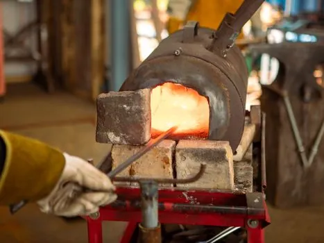
Specify the required output as tonnes per hour, define the metal-to-coke ratio, identify cold-blast or hot-blast operation, state the blast-temperature range, and request both shell plate diameter and finished internal working diameter. For the 10 t/h benchmark, require the supplier to demonstrate the 1,220 mm internal-diameter design point or justify an alternative through gas-flow, residence-time and combustion calculations [S3].
Hot-blast bids should state recuperator performance and the 400–600°C blast-temperature basis, while cold-blast bids should acknowledge the approximately 60% efficiency and the composition and temperature limitations associated with that route [S5]. The charge-bed and blower requirements should be developed together because the published 10 t/h design pairs the 1,220 mm diameter with a specified blowing rate [S3].
A traceable tender package should also require a metal-to-coke ratio calculation, because a diameter selected at one fuel ratio does not retain the same output if coke consumption, charge bulk density or blast conditions change. The most useful trackable signal is measured tap mass during steady production: cumulative tap weight versus cumulative time should form the straight-line segment used to confirm actual melting rate [S1].
For a first-pass estimate, use 1,220 mm internal diameter for 10 t/h at 8.1:1 only as a named reference design, not as a universal rule; then validate the selection against the 450–2,000 mm, 1–30 t/h commercial envelope and the selected combustion mode [S3][S4][S5].
