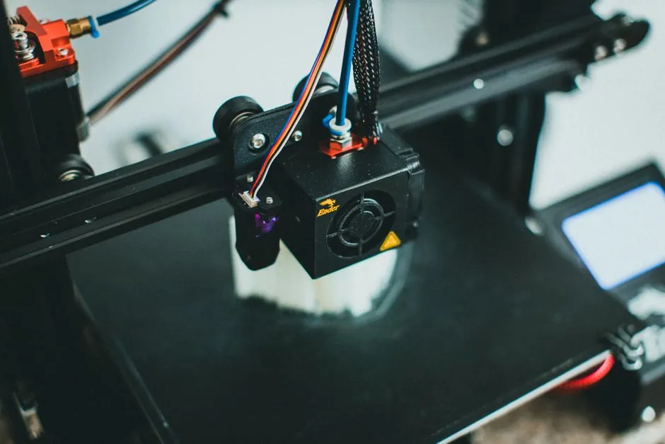
Across six major process families, material choice and build-size constraints are coupled, so a buyer must lock the process window before the alloy or polymer grade [S1][S4]. DMLS (direct metal laser sintering) yields parts whose mechanical properties approach an isotropic state, which is why the same material grade often shows different tensile and fatigue numbers between AM and wrought stock [S1].
For polymers, the decision tree runs through FFF/FDM (fused filament fabrication), SLA (stereolithography), and SLS (selective laser sintering), each with different minimum wall thickness, overhang tolerance, and support-removal overhead. Metal AM additionally splits into DMLS/SLM (selective laser melting), DED (directed energy deposition), and binder jetting, with build envelopes that range from roughly 100 mm cube desktop units to 500 mm+ industrial powder-bed platforms [S2][S4].
Process Family vs. Material Capability Map
FFF/FDM dominates large-format thermoplastic work because deposition rate scales with nozzle size, but layer adhesion is highly directional, so parts loaded across the Z-axis typically show 40-60% of XY tensile strength, a known anisotropy that drives most design rule changes [S2]. SLA delivers the smoothest surface finish (often Ra 0.4-1.6 micrometres without secondary finishing) and the finest feature resolution (down to roughly 0.05 mm on dental-class printers), but the cured photopolymer resin is brittle and UV-sensitive, so outdoor or load-bearing structural use is a poor fit [S1][S2].
SLS in nylon-12 (PA 12) is the workhorse for functional polymer prototypes because unfused powder acts as its own support, which removes most overhang-angle restrictions and lets engineers nest parts inside the build chamber at high packing density [S1]. For metals, DMLS and SLM share the same powder-bed physics and overlap heavily on materials (17-4 PH and 316L stainless, Ti-6Al-4V, Inconel 718, AlSi10Mg, maraging steel 1.2709), while DED handles larger deposition volumes and repairs but at coarser resolution, and binder jetting suits high-volume runs of small parts because the green part requires a separate furnace sintering cycle [S4]. The reference coverage of process families and their additive manufacturing material families is consistent with the additive manufacturing material classifications used across the industry [S1].
Sizing Rules of Thumb and Build Envelope Reality
Desktop FFF printers typically deliver build volumes of 200-300 mm on each axis, while large-format industrial FFF units reach 1 m on the long axis, which is why jigs, fixtures, and patterns are common in that format [S2]. Metal powder-bed systems sit in a tighter band: small-format DMLS machines are roughly 100 x 100 x 100 mm, mid-format units 250 x 250 x 300 mm, and the largest commercial powder-bed platforms reach 500 x 500 x 500 mm class, beyond which DED is the only practical option [S4]. Minimum feature size scales with laser spot and powder layer thickness, typically 0.04-0.10 mm for DMLS/SLM and 0.10-0.30 mm for DED.
Wall thickness is the single most common DfAM violation. FFF tolerates roughly 1.0-1.2 mm minimum walls, SLA and SLS drop to 0.6-0.8 mm, and DMLS metal walls should stay above 0.8-1.0 mm to avoid over-sintering and powder entrapment [S1][S2]. For broader context on how build envelope drives part geometry on adjacent production equipment, the same envelope-driven thinking shows up in PE pipe selection for school sitework: DR, material and sizing map, where outside-diameter and DR ratings gate what fits a given trench and SDR class. The metal-powder sourcing side is covered in the metal powder suppliers and manufacturers 2026 sourcing map, which is the natural upstream reference for any DMLS or binder-jetting program.
Mechanical Duty and Anisotropy by Process
Metal AM parts from DMLS/SLM reach 90-100% of wrought tensile strength in XY, with elongation at break for 316L typically in the 30-50% range after hot isostatic pressing (HIP) and stress relief, versus 60% for wrought 316L plate [S1]. Z-direction tensile strength is the weak axis on as-built DMLS and is the main reason critical fatigue-loaded parts are HIP'd at roughly 1160-1200 degrees C and 100-200 MPa for 3-4 hours to close internal porosity [S4]. FFF parts show similar directionality: a well-tuned print in PETG or polycarbonate can hit 70-90% of injection-molded tensile strength in XY but only 40-60% in Z, which is why load paths must be aligned to the build plane wherever possible [S2].
For comparison across the polymer and metal families on a fixed set of four selection axes (cost, max part size, isotropy, surface finish), the working numbers are: FFF/FDM - low cost, 1 m+ envelope possible, strong anisotropy, Ra 5-20 micrometres as-built; SLA - mid cost, 300 mm envelope, moderate isotropy for static loads, Ra 0.4-1.6 micrometres; SLS (PA12) - mid cost, 300-400 mm envelope, best polymer isotropy, Ra 6-12 micrometres; DMLS/SLM - high cost, 500 mm class envelope, near-isotropic after HIP, Ra 5-20 micrometres as-built, down to 1-5 micrometres after bead blasting or electropolishing [S1][S2][S4].
When Additive Manufacturing Is the Wrong Choice
AM loses to CNC or injection molding when production volume exceeds roughly 50-500 units for a single polymer part, because per-part cost falls steeply with conventional tooling amortization beyond that band [S2][S4]. It is also a poor fit for parts requiring optically clear polycarbonate or chemically resistant PEEK in continuous service, since most high-temperature AM polymers top out at 150-250 degrees C continuous and cannot match the optical or chemical durability of injection-molded grades [S1]. Pure cosmetic mirror-finish surfaces are similarly a poor fit: as-built AM surfaces sit at Ra 5-20 micrometres, and post-processing to Ra below 1 micrometre adds labour cost that often exceeds the part value [S1][S4].
Material waste is one of the AM advantages that gets overstated. DMLS uses roughly 5-10 kg of powder per build cycle, and the unmelted powder can be reused only 3-8 times before oxygen pickup and PSD (particle size distribution) drift push it out of spec, at which point the user is paying roughly 60-80% of virgin powder cost for recycled feedstock [S4]. For ductile metals, support removal in DMLS can eat 10-30% of the as-built mass, and the EDM or machining step needed to clean those supports is a real cost line item that designers forget when they push aggressive overhangs.
Design-for-AM Rules That Drive Material Choice
Overhang angle is the first DfAM lever. FFF tolerates roughly 45 degrees without supports, SLA needs 20-30 degrees, and DMLS metal prints hold 45 degrees, with self-supporting lattices viable down to 20-30 degrees if the engineer accepts surface roughness penalties [S2]. Wall thickness must be uniform wherever possible: a jump from 2 mm to 6 mm in the same wall invites distortion and residual stress, particularly in DMLS where thermal gradients drive warpage and support scarring.
Orientation matters as much as material. A bracket loaded in shear prints stronger rotated 45 degrees onto the build plate than flat, because the layer-bond planes no longer align with the load path [S1]. Generative-design and topology-optimization tools feed directly into DfAM and can cut mass 20-60% on brackets and housings, but the resulting organic lattices often require metal DMLS or SLS PA12 to print, which is the moment material choice locks in based on the optimizer's output [S2]. For process-and-machinery buyers thinking about downstream cells, the molding line working principle: the five stages that define every plastic and foundry cell provides a useful contrast to AM's single-step part formation. Sourcing metal powder for DMLS and binder jetting benefits from a current vendor map, which is laid out in the metal powder suppliers and manufacturers 2026 sourcing map.
Material-Selection Checklist Before You Commit
Lock the process first, then the alloy or polymer grade, not the reverse. Define the load case: static, fatigue, impact, thermal, and chemical, then match to a material whose published datasheet numbers sit at least 20% above the requirement. For metal AM, the published numbers almost always assume post-build HIP and stress relief, so a buyer who skips that step must derate the design numbers accordingly [S4].
Validate powder reuse policy and traceability: most ISO 9001 and AS9100 certified AM job shops issue a powder batch certificate with chemistry, PSD, and flow data, and the buyer should retain those for each build [S4]. For polymer AM, validate the support removal and finishing cost separately from the print cost, because for SLA and FFF parts those two lines can run 30-100% of the print price and decide whether AM beats conventional methods. Final shortlist rule: pick the lowest-cost process that meets the duty and surface finish, then pick the cheapest grade within that process family that meets the mechanical numbers, and only step up to DMLS or DED when the part cannot be made any other way.
Trackable next signals: a) DMLS build envelope crossing the 800 mm mark on at least one commercial platform, which would extend AM reach into larger structural components; b) recycled-powder reuse counts climbing past 10 cycles without chemistry drift, which would reset the per-part powder cost line; c) more shared ASTM/ISO coupon datasets for as-built versus HIP'd mechanical properties, which would remove the derate step that currently forces buyers to ask the job shop for raw test bars.
Spec-level background on the components involved: linear guide, and crossed roller guide.