
An injection unit, a mold assembly, and a clamping unit form the working core of every plastics molding line, with horizontal reciprocating-screw machines dominating above 50 tonnage because the screw doubles as plunger and feeder [S2].
For a foundry line the same five functional blocks apply, but the compaction block uses bentonite-bonded sand and a flask instead of polymer melt, and demolding uses a separate station rather than a moving platen [S4]. The encyclopedia entry on molding treats both families as variants of a single shaping cycle.
Plastification: screw-as-plunger versus extruder barrel
The screw in an injection machine serves two non-substitutable roles, acting as a plunger that generates injection pressure during forward stroke, and rotating to feed and melt granules during the metering phase [S2]. A check valve at the screw head prevents backflow during injection, so pressure at the nozzle reflects the cylinder thrust, not screw rotation [S2].
In a blow molding cell, plastification is decoupled into an extruder that continuously produces a parison, a molten tube that hangs between mold halves before inflation, so the line is sized in kg/h of extruder output rather than in shot weight [S3]. For sand foundries the analogue is a sand mixer feeding a measured batch of bentonite-bonded sand to the molding station at every cycle [S4].
Fill and compaction: the two forces that decide quality
Foundry practice has shown that bentonite-bonded sand develops higher post-compaction compressive strength on the squeeze side than on the pattern side, because friction at the flask wall and pattern contour diverts a portion of the applied force along the force transmission path [S4]. This is the physical reason two-stage compaction, including squeeze plus a pulsed or air-flow second step, exists in modern automatic molding lines.
In injection molding the same force-balance logic appears as the pairing of clamping force (tonnage) and injection volume (grams of polystyrene equivalent). Boyan's reference table links machine tonnage to grams of shot, with no strict one-to-one correspondence because part geometry and projected area shift the demand on the clamping side independently of shot size [S2]. Selecting a machine on tonnage alone is a common specification error documented across both plastics and foundry cells [S2][S4].
Clamping and demolding: the four-classification axis that drives machine choice
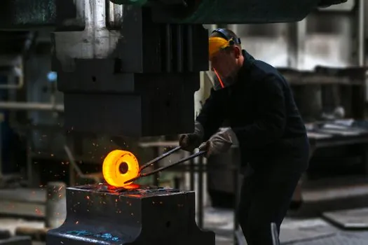
Foundry molding machines are classified along four major axes: demolding principle, drive concept (manual, pneumatic, hydraulic), number of stations (simplex versus duplex), and compaction method (one-stage versus two-stage) [S4]. A fifth axis, rigid versus flexible pattern-plate connection, is decisive for job-shop flexibility, since a rigid connection ties one machine to a single flask size [S4].
On the plastics side the static pressure molding machine family extends the same logic by replacing mechanical squeeze with a pressurised gas head that equalises compaction force across the flask face, which removes the rear-versus-pattern strength gradient seen in squeeze-only cells [S4]. Demolding on a shell line is handled by a dedicated rollover or strip station, separating the parting function from the compaction function, which is the structural difference versus an inline shell molding machine cell [S4].
Process families compared on four selection criteria
For a buyer comparing the three dominant process families, the decision pivots on four criteria. Material state: polymer melt below 300 °C for injection, parison at similar temperature for blow, and ambient sand for foundry [S2][S3][S4]. Production rate: injection is discrete (seconds per cycle), blow is semi-continuous, and a foundry duplex machine runs two stations in parallel to hide demolding time [S2][S3][S4]. Key spec pair: shot weight in grams versus clamping tonnage for injection, parison mass in grams versus mold-cavity count for blow, and flask size in millimetres versus compaction force in kN for foundry [S2][S3][S4].
Typical part envelope: thin-wall packaging under 1.5 mm wall and hollow containers for blow, structural parts with 0.5–6 mm wall and tight tolerances for injection, and metal castings up to several tonnes for foundry sand lines [S2][S3][S4]. No single family wins on all four; injection wins on tolerance, blow on hollow geometry, foundry on metal casting material, which is why many plants run more than one process family rather than consolidating [S2][S3][S4].
Where these lines fit a 2026 spec-first buyer
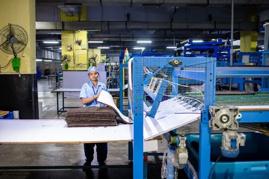
For shop-floor engineers the 2026 specification discipline is unchanged from the prior decade: state the cycle-time target in parts per hour, the part weight in grams, the projected area in cm² for clamping, and the required mould strength in kPa for foundry, then select from the four-classification matrix [S4]. A correctly specified conveyor sorting line downstream must match the upstream cycle time, otherwise the bottleneck shifts from the molding cell to material handling.
Two trackable signals to watch: adoption of two-stage compaction modules on greenfield foundry cells, driven by the documented rear-versus-pattern strength gradient [S4], and continued displacement of hydraulic by servo-electric clamping units in injection, where the energy saving is large enough to justify retrofit on lines above 200 tonnage [S2]. Buyers building a 2026 capex list should request the tonnage-versus-grams reference curve from any short-listed OEM, since the absence of that curve is itself a procurement red flag [S2].
Background reading: Filling Machine Sizing and Selection: Viscosity, Throughput, and Spec Map.