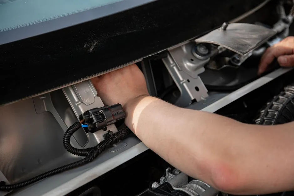
A correct solenoid coil install is dictated by four numbers on the nameplate: insulation class (F or H), ingress protection (IP65 typical for DIN-connector types), duty cycle (100% ED for continuous service), and the mounting torque figure specified for the armature nut and the cable gland, with Danfoss BB/BE/BF/BG/BN coils calling for 50–60 Ncm on the coil nut and 250–375 Ncm on the PG11 gland [S3].
Get any one of those wrong and the failure mode is predictable: an under-torqued coil nut burns the encapsulation, an over-torqued PG11 cracks the housing, an F-class coil in a high-ambient cabinet goes into thermal runaway, and a 100% ED coil driven by a PWM dimmer instead of a clean switched line never reaches pull-in. The field map for these components is laid out in the Solenoid Coil Types and Classifications spec field map.
Read the nameplate before you pick up a spanner
The four-coil 100C/200C/2W200C/2WO250C/2W350C family from a typical pneumatic line stocks F-class or H-class insulation, all rated 100% ED, with a DIN 43650C connector carrying an LED indicator and a strain-relief nut that must be hand-snug then given a controlled quarter-turn [S2]. H-class (180 °C) coils are the right pick where ambient sits above roughly 40 °C or where the coil is fully enclosed in a cabinet with no airflow, while F-class (155 °C) is acceptable for general pneumatic manifolds in a control room.
Coil voltage must match the supply, not the valve: AC coils are interchangeable across AC voltages by swapping the coil alone, and DC coils swap across DC voltages on the same rule, but you cannot convert an AC coil to DC service (or vice versa) by rewiring, because the magnetic circuit and the inrush/holding current profile are designed for one supply type [S1]. Current is inversely proportional to voltage on the same coil, so a coil drawing 0.5 A at 120 V will draw 0.25 A at 240 V and 0.125 A at 480 V, which is the right number to use when sizing the branch-circuit protection [S1].
Wiring rules that prevent sticking and burnouts
The coil is a two-wire device, but how you switch it matters as much as the wire size: install the switch in the hot leg of a 120 V circuit, and use a double-pole switch on 240 V or 480 V circuits where both legs are hot, because even a few milliamps of leakage through a single-pole switch can hold the armature in and overheat the coil [S1]. On a motor with a step-control starter, feed full line voltage to the coil immediately on start, do not ramp it, since partial-voltage start leaves the coil in the high-inrush region for too long.
Use 18 AWG wire as the default lead size (longer continuous leads are available as an option), keep the run as short as practical to limit voltage drop, and route the leads away from the solenoid body itself; the encapsulation is rated for the service temperature but the lead exit is the most common cracking point when cables are pulled sideways [S1]. For DC service the polarity is meaningful: red or plus-marked to the positive leg, black or minus to negative, and confirm with a multimeter before applying power because a reverse-polarity DC coil will not seat the plunger cleanly and may buzz [S5].
Mounting sequence: surface, bracket, coil, connector
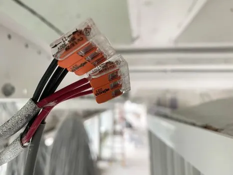
Pick a mounting location that is clean, dry, away from heat sources, and clear of vibration, then make the surface flat; an uneven surface flexes the coil housing under torque and cracks the encapsulation [S5]. Where the coil ships with a mounting bracket, fix the bracket to the coil first with the supplied screws, then align to the surface holes and torque the mounting hardware to the bracket spec, not to the coil nut spec, because the two torques are different and over-torquing the bracket screws will warp the magnetic frame.
For Danfoss BB/BE/BF/BG/BN, the documented sequence is to slide the coil over the armature tube, fit the washer and nut, and torque the nut to 50–60 Ncm with a Torx TX10, then dress the cable through a PG11 gland torqued to 250–375 Ncm so the cable cannot rotate inside the body [S3]. On coil families that include a captive spade or DIN plug (Danfoss type A rated IP00/PD3, type A1/A2 rated IP65/PD3 with cable plug) the connector choice has to match the environmental spec, not the convenience of the installer [S6].
Acceptance checks and when not to repair
Before energising, measure the coil resistance with a multimeter and compare to the nameplate; an open circuit means a broken internal wire (replace, do not repair), a short to the housing means a punctured encapsulation (replace), and a resistance within ±10 % of nameplate with no path to ground is the pass condition [S5]. Apply rated voltage and listen for a single clean pull-in click, not a buzz; a buzz on AC means low voltage, a contaminated plunger tube, or a missing shading ring, and on DC it typically indicates a weak supply or a sticky plunger, both of which need the coil removed from the valve for diagnosis.
Do not attempt to re-encapsulate a field coil; the OEM encapsulation is vacuum-potted and field repair cannot restore the original moisture/oil/chemical resistance, and the original rating (F-class or H-class, IP65) is invalidated the moment the housing is opened [S1]. Replace, not repair, any coil that has been dropped, that shows swelling of the encapsulation, that smells of burnt varnish, or where the lead insulation has hardened and cracked; the failure mode in each case is thermal, and the next event is an open circuit under load.
Sourcing and standards to pin on the purchase order
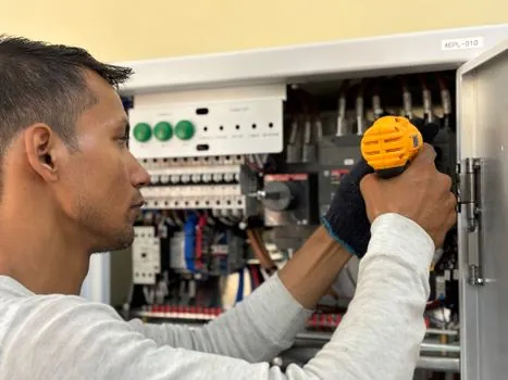
On the PO, name four things: the coil family code (for example Danfoss BB, BE, BF, BG, BN or the BZ/HE 0.5/1.0/1.5/4.0/8.0 series with H₁ from 20 to 48 mm and ØD from 7 to 10 mm), the voltage and frequency (10 W on AC, 18 W on DC as the standard Danfoss power bands), the connector form (spade, DIN plug, terminal box, cable), and the IP/insulation class [S7][S8]. For pneumatic-panel work, the 100C/200C F-class IP65 DIN 43650C with LED is a sensible default, and the 2W-series H-class IP65 is the upgrade for hot or enclosed panels [S2].
Coil specification decisions intersect with valve and transformer sizing on the same panel; the Power Transformer Sizing and Selection 2026 spec workflow covers how to keep the solenoid supply rail clean, while a solenoid valve perspective frames the valve-side acceptance criteria and an air solenoid valve view covers the pneumatic-service end of the install. The coil itself, as the wound magnetic component, is detailed in the solenoid coil reference.
Track two signals over the next quarter: a) whether your supplier has restocked the 18 W DC variants in the BB/BE/BF/BG/BN family, since DC coils have the longest lead times in this category, and b) the IP65-vs-IP67 mix on incoming shipments, because several Asian lines have shifted the default cable-plug rating without a nameplate change.