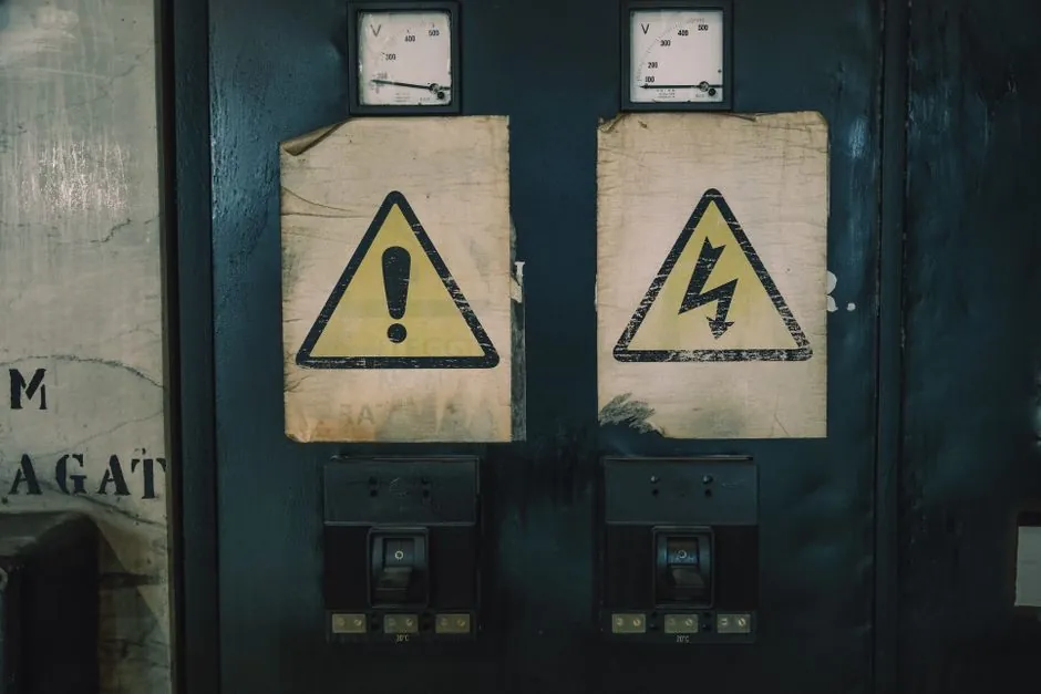
An SPD is specified first by the system it sits on: AC or DC, nominal voltage, and short-circuit current availability at the point of connection, because a clamp rated below the system voltage will fail open or short, while a clamp rated far above it will let the transient through to the load [S3][S4].
Three specs drive almost every datasheet comparison: clamping voltage (the residual let-through, in V), discharge capacity I_n or I_imp (in kA, the surge current the device can divert repeatedly or once), and response time (typically sub-nanosecond for MOV-based units, with TVS diodes faster) [S4]. For industrial buyers, the second-tier questions are certifications (IEC/EN 61643-11, UL 1449, CE, TÜV, CB) and the topology: Type 1 at the service entrance, Type 2 at the sub-distribution board, Type 3 at the equipment terminal [S3].
Match the SPD to the system, not the other way around
Industrial facilities most often run 230/400 V AC three-phase or 120/240 V single-phase, which points procurement at a Type 2 SPD sized to the available short-circuit current (Isc) at the busbar and to the impulse current (I_imp) the standard requires at that location [S3].
Solar PV strings, battery storage, and EV DC fast chargers need a DC SPD whose maximum continuous operating voltage (Uc) covers the string open-circuit voltage at the coldest expected cell temperature, because a DC arc does not self-extinguish the way an AC arc does at current zero [S3]. Pairing an AC-rated MOV module on a DC string is a common procurement error and the most common cause of field failure on solar sites.
The 1 to 30 microsecond transient envelope and the 6 kV/0.5 kA to 20 kV/10 kA exposure window defined by IEEE C62.41.2 location categories (A, B, C) are the upstream basis for picking Type 1, 2, or 3 [S4]. A surge protective device selected purely by joule rating, without those location categories, will under- or over-spec the busbar.
Type 1, Type 2, and Type 3: a layered, criteria-based comparison
Layering is the standard industrial design: Type 1 at the service entrance handles direct lightning current (10/350 µs waveform, I_imp 12.5 kA or more per phase), Type 2 at the sub-distribution handles the residual 8/20 µs switching surge (I_n 20 to 40 kA typical, with I_max to 65 kA or 100 kA), and Type 3 at the equipment clamps the let-through to the load's immunity level, often below 1.5 kV [S3][S4].
Two practical comparison lines: first, on discharge capacity, an industrial-grade Type 2 SPD typically sits in the 20 to 65 kA I_n / 40 to 100 kA I_max band, while a Type 1 module is rated in I_imp and a Type 3 in Uoc (the combination wave open-circuit voltage the test generator delivers), so comparing kA across types is meaningless [S3]. Second, on location, Type 1 is mandatory where the building has an external lightning protection system or an overhead service drop, Type 2 is the default for any indoor distribution board without direct lightning exposure, and Type 3 is added when the load's surge immunity is below 1.5 kV or when cable runs from the Type 2 to the load exceed roughly 10 m.
Cheap multi-outlet power strips with a small MOV and a neon lamp are not a Type 3 equivalent; they typically lack a verified Uoc rating, lack thermal disconnection, and degrade silently until the MOV goes short, which is a fire risk [S2]. Treat any device without a printed IEC/EN 61643-11 or UL 1449 third-party mark as a power strip, not an SPD.
Discharge capacity, let-through voltage, and the real numbers on the datasheet
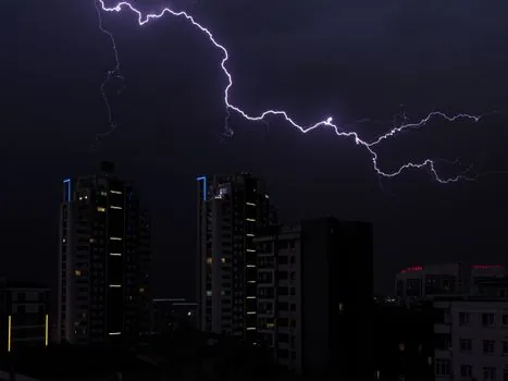
For an industrial plant on an unstable grid or with frequent switching transients, 40 kA I_n / 100 kA I_max at 8/20 µs is a common baseline; sites with direct lightning exposure or large motor switching (VFDs, large HVAC chippers, capacitor banks) should be specced to 12.5 kA I_imp (10/350 µs) at the service entrance [S3].
Clamping voltage (Up, the voltage measured at the SPD terminals during the test) is the load-relevant number, not the joule rating; for 230 V AC systems a Up of 1.0 to 1.5 kV is typical, and the connected equipment's surge immunity (usually 1.5 to 2.5 kV for industrial electronics per IEC 61000-4-5) must sit above Up, with cable impedance between SPD and load subtracted to give the actual stress on the equipment [S4].
Joule rating is energy absorption, useful for consumer strips, but the more honest industrial figure is I_n / I_max / I_imp, because kA describes what the device can shunt repeatedly without failing, while joules describe a one-shot, non-replaceable MOV [S2][S4]. Two SPDs with the same joule figure can have order-of-magnitude different kA ratings because the waveform and the test method differ.
End-of-life, auto-shutoff, and replacement intervals
Every MOV degrades with each surge it diverts, and there is no public way to read remaining life from the outside, which is why the practical guidance is an auto-shutoff (thermal disconnection) that opens the circuit when the MOV reaches end-of-life, plus a status indicator so the operator knows the device has quit protecting [S2].
Replacement intervals in service: average 3 to 5 years for point-of-use surge strips and 5 to 10 years for whole-home or panel-mounted units, dropping to roughly 2 years in homes or cabinets with frequent brownouts or unstable grid events, because each brownout is a switching transient that ages the MOV [S2].
For sites with vital loads (CPAP-class medical, hard-disk storage, process controllers that cannot tolerate a power interruption), an SPD is necessary but not sufficient; the spec must add a UPS with surge protection, because a sudden loss of power creates a separate, unprotected failure mode that an SPD will not cover [S2]. An SPD is over-rated if the failure mode it is asked to handle is actually a sustained overvoltage or a sag, both of which are utility events outside the microsecond transient window the SPD is built for [S4].
Standards, certifications, and what to demand on the datasheet
For international industrial projects, demand IEC/EN 61643-11 (the product standard for low-voltage SPDs, with Type 1/2/3 classes), and, depending on the market, UL 1449 (North America), CE under the LVD and EMC directives, plus TÜV or CB scheme reports for cross-border acceptance; RoHS and REACH statements are the environmental baseline [S3].
For North American facility work, IEEE C62.41.2 location categories A/B/C define the 6 kV/0.5 kA to 20 kV/10 kA exposure envelope that drives Type selection, and IEEE C62.45 describes the test methods, so any SPD datasheet that does not list C62.41.2 location testing is missing a piece of the compliance trail [S4].
Certifications to ask the vendor to provide a current certificate number for, not a generic claim: CE, TÜV, CB, and RoHS for industrial, plus UL 1449 if the project ships to the US, and a Declaration of Performance (DoP) under the CPR if the SPD is sold as a construction product in the EU [S3]. A copy of the test report with the I_n, I_max, I_imp, and Up values stamped by a third-party lab is the difference between a verified SPD and a generic MOV in a DIN-rail housing.
Who an SPD is for, and who should pick something else
SPDs are for protecting equipment with semiconductor content (PLCs, VFDs, instrumentation, network gear, medical and lab electronics) from microsecond-scale voltage transients on the AC mains or DC bus; they are not for limiting sustained overvoltages from a lost neutral, not for protecting against a direct lightning strike to the structure, and not a substitute for a lightning protection system (LPS) with down-conductors and earth termination [S4].
Buyers should not pick a consumer-grade power strip for a control panel, even if the joule number is impressive, because the strip has no verified I_n or Up, no thermal disconnection, and no IEC/EN 61643-11 mark; conversely, a heavy Type 1 module on a sub-distribution board inside a building with no external LPS is over-spending on I_imp that will never see a 10/350 µs event [S3].
Track the same shortlist logic used in adjacent spec-driven buys, like the bearing procurement strategy or industrial relay sizing and selection: write the duty first, write the standard second, write the test method third, then pick the part number. The signal to watch over the next quarter is the EN 61643-11 maintenance cycle and any tightening of Up limits for Type 2 modules driven by IEC 61000-4-5 immunity updates on industrial equipment.
Spec-level background on the components involved: protective clothing, and pressure transmitter.