An installed turbine gas meter can be checked for rotor drag with an in-line spin-down test, avoiding removal of the meter cartridge [S1][S4].
Three repetitions averaged for comparison with the meter baseline are the core diagnostic method, with testing performed before lubrication and the system depressurised [S2][S3][S8].
What the turbine-meter spin test measures
A spin test accelerates the rotor to a defined speed and then records the time required for it to coast down to zero or a specified lower speed [S5]. On an installed meter, the pulse generator detects successive blade passages while the rotor stops [S4].
Spin time is an indirect condition indicator, not a direct bearing-diameter measurement. Shorter coast-down time points to greater mechanical drag, which can arise from bearing wear, shaft issues, rotor deposits, or installation influences [S4][S8][S9]. A long time alone does not prove that the bearings are healthy because residual lubrication, contamination, flow conditions, and the starting method can change the result [S2][S4].
The in-line method measures rotor spin time without removing the meter cartridge [S1]. It therefore suits installed meters where shutting down and removing the instrument would be disproportionate. The method does not replace a physical inspection when the rotor will not turn freely, produces grinding noise, or shows other mechanical damage [S6].
Test sequence for repeatable results
Depressurise the system before measuring spin-down time, and complete the test before lubricating the meter [S2][S4]. Lubrication temporarily reduces spin time while excess oil drains from the rotor, so a post-lubrication result is not comparable with a dry baseline unless the procedure defines that condition [S2].
Run at least three repetitions and calculate the average spin time [S3][S8]. IS 15676 states the same repetition principle for turbine gas-meter spin tests [S8]. Keep the rotor starting condition, trigger method, timing endpoint, and meter configuration consistent between tests, because an installed wheel must be brought to speed in its installed condition for the result to represent the service configuration [S4].
Do not force the rotor if it is locked or mechanically rough. Remove the rotor for a hand-spin inspection when free rotation cannot be achieved; restricted motion or grinding noise points to probable bearing or rotor damage [S6]. For applications where operating installation and flow disturbances affect the measurement, consider a reference installation with two turbine meters or one turbine and one ultrasonic meter, while recognizing that pulsation, resonance, and inlet-profile distortion can also produce deviations [S4].
Comparing spin time with the meter baseline
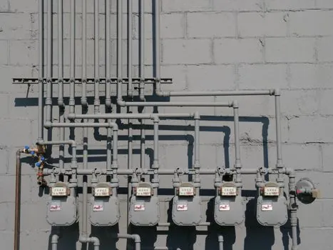
Spin-time results have value only when compared against an accepted reference for the same meter, including the rotor, bearing condition, test method, and endpoint. IS 15676 identifies decreased spin time as a condition commonly associated with increased turbine-wheel shaft or bearing friction [S8].
Use a three-level comparison: first, compare the three measured runs with each other; second, compare their average with the manufacturer’s baseline; third, investigate any decline using meter accuracy or field verification. The in-line monitoring concept links measured spin time to the corresponding change in meter accuracy, and field trials in Ohio and Massachusetts produced repeatable results [S1].
This comparison separates random test scatter from a sustained change. A falling average paired with a meter-factor shift is more actionable than a single short run. For a broader measurement view, the turbine flow meter can be checked against its specified operating and base conditions, including the relevant flow and pressure values.
Spin test, bearing diagnosis, or meter verification
Spin testing is the practical first-line option for an installed turbine meter because it measures coast-down time without removing the cartridge [S1][S4]. Direct rotor inspection is better when the rotor does not rotate freely, makes grinding noise, or the meter has been opened or lubricated under an uncontrolled procedure [S2][S6].
Advanced inline diagnosis is better when the meter has a pulse generator, blade count, bearing dimensions, and enough operational data to analyze pulse-period behavior [S4]. The Elster-Instromet diagnostic uses a pulse generator scanning the turbine wheel blades, along with design parameters such as the number of blades and ball-bearing sizes, to show bearing damage, calculate bearing wear, and identify system-related influences [S4].
Field proving is the stronger choice for acceptance or calibration work, while spin testing is better for periodic condition surveillance. The criteria are therefore different: spin test for repeatability and change from baseline; inline pulse analysis for bearing and system influences; physical inspection for visible damage; and field proving for accuracy verification. These methods are complementary, not interchangeable.
Lubrication, contamination, and flow effects
Oil is a controlled variable in the test sequence, not an incidental maintenance action. The GTX/GTS installation instructions specify the spin test before lubrication because excess oil temporarily lowers spin time [S2]. Fundamental turbine-meter guidance also calls for lubrication after a low result followed by several rotor spins to work the lubricant through the bearing area [S3].
Deposits on the rotor can create imbalance or added drag, while bearing wear gradually raises friction [S9]. As friction increases, the minimum measurable flow rises and the meter factor shifts downward [S9]. This does not make the meter safe to operate indefinitely at lower flow: a meter already outside its specified range can produce unreliable volume measurement even when the rotor still spins.
Installed flow effects can also alter the diagnosis. Pulsations and resonance may speed up or slow the rotor, while flow-profile distortion affects comparative meter readings [S4]. The clamp-on ultrasonic flow meter can serve as an independent reference in suitable piping, but a flow meter comparison still needs matched pressure, temperature, and flow conditions.
Sourcing, safety, and the maintenance record
IS 15676 (2006), Flow measurement of natural gas by turbine meters, requires repeated spin tests and an average time, making a documented baseline part of the applicable turbine-meter test procedure [S8]. For field work, follow the manufacturer’s approved sequence, local isolation procedure, and applicable site safety requirements before depressurising or handling the meter.
Record the meter serial number, rotor configuration, line pressure, line temperature, test date, starting method, endpoint, and all three individual spin times. Calculate the average and compare it with the accepted baseline. If the result declines, repeat under the same conditions before removing the meter or applying lubricant, then escalate to inspection or field proving [S3][S6][S8].
For a broader comparison of turbine-meter selection and sizing constraints, sizing a turbine flow meter around its minimum linear flow rate covers the operating range that must be considered before declaring a degraded meter acceptable.