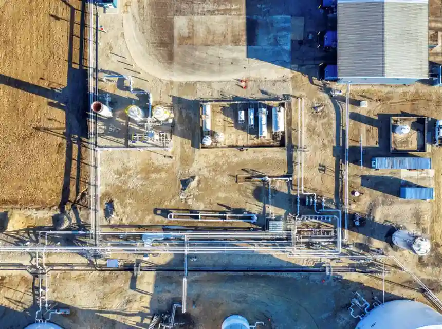
A centrifugal steam separator is specified to remove entrained moisture from saturated or superheated steam lines, with published charts calibrated to 99% capture of droplets larger than 10 microns [S4].
Selection is governed by three coupled variables: saturated steam mass flow, operating pressure, and acceptable pressure drop across the vessel. For a design case at 180 psi g (12.4 bar g) and 1,100 lb/h (500 kg/h), Spirax Sarco S5/S6 charts show a 1¼ in separator running near 60 ft/s (18 m/s) line velocity with approximately 0.5 psi (0.03 bar) pressure drop [S3].
Two accepted sizing methods: droplet settling vs. Souders-Brown
Engineers size gas-liquid separators by either the droplet settling theory method or the Souders-Brown approach, both of which yield a maximum allowable superficial velocity that the vessel must not exceed at design flow [S6].
Droplet settling equates the terminal settling velocity of a target droplet size (commonly 100-150 microns for bulk knock-out) to a fraction of the gas superficial velocity, with the design K-factor adjusted for pressure, density, and demister efficiency. The Souders-Brown correlation compresses those terms into a single empirical constant K_SB, historically in the 0.1-0.4 ft/s range for vertical separators without a mist eliminator, and rising above 0.5 ft/s when a knitted mesh pad is fitted downstream [S6]. Because the Souders-Brown K constant is purely empirical, Moshfeghian recommends corroborating it against droplet settling theory whenever the service diverges from hydrocarbon three-phase duty [S6].
Steam chart axis logic: pressure, flow, and ΔP together
Steam sizing charts use pressure on the vertical axis, mass flow on the horizontal axis, and differential pressure on a secondary Y-axis, with one diagonal performance curve per vessel size [S4]. The procedure is to draw a horizontal line at the design PSIa to the ΔP axis, then a vertical line at the design lb/h; the separator size is read where the two lines intersect the nearest diagonal performance curve [S4].
The original FD Separators performance data traces back more than 50 years of laboratory testing on steam and compressed air, and the resulting charts and formulas underpin most current web-based sizing calculators [S4]. Since centrifugal vortex separators have an infinite turndown ratio, separation efficiency is maintained even at the lower pressures experienced during start-up and shut-down, provided the unit was correctly sized for the design case [S4].
Velocity and pressure drop: the 60 ft/s design target
Steam velocity at the separator inlet should be held near 60 ft/s (18 m/s) for the S5/S6 size range, with line velocity read off the chart as a function of pipe size and saturated steam flow [S3]. For the 1¼ in (DN32) unit at 1,100 lb/h and 180 psi g, the chart returns approximately 60 ft/s; for the ½ in unit at the same conditions the velocity climbs above 100 ft/s, which is outside the shaded "better than 99% separation efficiency" band [S3].
Pressure drop is read by plotting the intersection of the chosen separator size with the line velocity. At 180 psi g and 1,100 lb/h, a 1¼ in S5/S6 separator incurs about 0.5 psi (0.03 bar) loss, which is generally acceptable on a 180 psi distribution main [S3]. Wright-Austin's saturated steam capacity chart tops out near 10,000 lb/h on a 6 in line and falls to 220 lb/h on a ½ in line, with all curves anchored to the same SCFM conversion [S7].
Compressed air cross-check: same vessel, different axes
The same physical S5/S6 vessel is rated on a separate compressed-air chart, but with volumetric SCFM on the horizontal axis instead of steam mass flow [S3]. For 100 SCFM at 100 psi g, a 1¼ in separator again sits inside the 99% efficiency shaded band with ΔP of about 0.15 psi (0.01 bar); pushing to 350 psi g and 350 SCFM on a 1 in body lifts velocity toward 120 ft/s and ΔP to roughly 3 psi (0.2 bar) [S3].
Because the air and steam curves are derived from the same physical test matrix, the vendor recommends that the air chart be used for any non-steam gas service, including nitrogen, CO2, and natural gas, with appropriate compressibility adjustment [S4]. A cyclone separator sized on the steam chart and then operated on hot air at the same mass flow will over-predict capacity, since volumetric flow rises with temperature at constant mass flow.
Where centrifugal separators fail: high velocity, fouling, and pulsating flow
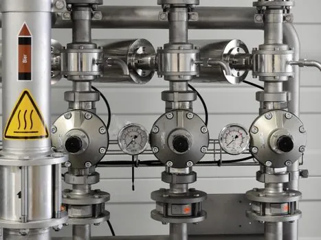
Performance drops sharply when the unit is fed flow above its design velocity or mass, because re-entrainment of the separated film on the vessel wall begins to dominate capture efficiency [S5]. TLV's published guidance is explicit: a separator's performance decreases if it is faced with a flow of higher velocity or mass than it is designed to handle, which is why the steam chart's "shaded band" exists [S5].
Three duty classes routinely violate that envelope and should be redirected to alternative internals. First, superheated steam with no entrained moisture is wasted capital on a centrifugal, since there is no coalescing film to throw off; a simple inline silencer or none at all is sufficient. Second, fouling or scale-forming feedwater (e.g. high-hardness boiler make-up) blinds the vanes within weeks, and a steam trap station placed downstream will not compensate for carryover slugs. Third, reciprocating-compressor discharge or PRV-downstream lines carry pulsating flow, which throws the vortex off-tune; a baffle-type or mesh-pad separator with a larger residence volume is the standard fix.
Selection shortlist: 1,000 lb/h to 10,000 lb/h at saturated steam
For saturated steam distribution headers in the 1,000-10,000 lb/h range, the practical shortlist is the FD Separators centrifugal line, the Spirax Sarco S5/S6 family, and the Wright-Austin 316L stainless cyclone. All three publish charts grounded in the same droplet-settling physics and rate at 99% capture above 10 microns [S4][S3][S7].
A side-by-side on four decision criteria reads as follows: (1) Line size fit, where FD and Wright-Austin offer ½ in through 6 in in matching increments and Spirax Sarco mirrors the same envelope; (2) Pressure drop, where the Spirax S5/S6 chart returns 0.5-2 psi (0.03-0.14 bar) across its working band versus 0.3-1 psi (0.02-0.07 bar) for FD's similar-dimension units at matched conditions [S3][S4]. (3) Material, where 316L stainless is standard across all three for clean steam, with carbon steel offered for utility headers; (4) Lead time and documentation, where Spirax Sarco ships the pre-printed TI-S99-10-US chart as part of the data packet [S3].
For a small clean-steam skid under 200 lb/h, the ½ in or ¾ in body on the S5/S6 chart is the right pick, because larger vessels cannot throttle down to maintain 60 ft/s without an external bypass [S3]. For a 10,000 lb/h distribution main, the 4 in or 6 in body is mandatory, and the design should be cross-checked against the air chart at the same volumetric flow to confirm the ΔP envelope [S3]. Trackable signals to confirm sizing post-installation: upstream pressure gauge vs. downstream pressure gauge at design load, with ΔP target 0.5-1.0 psi (0.03-0.07 bar) for clean steam service; carryover sampling per ASTM E1342 or equivalent at the first PRV downstream. Cross-reference on bearing hardware for header support frames is covered in slewing bearing selection practice.