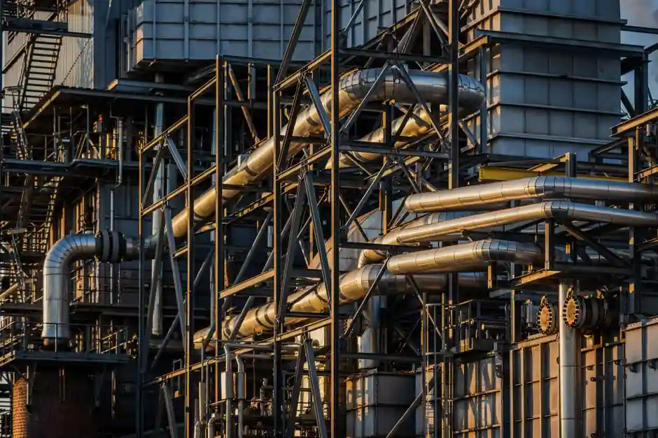
A steam separator is a passive mechanical device installed in a steam line to strip entrained water droplets from flowing steam before the steam reaches control valves, flowmeters, or heat exchangers [S1][S2].
Selection depends on six engineering inputs: steam pressure, steam flow rate, pipe size, operating temperature, inlet moisture content, and the allowable pressure drop across the vessel [S1]. In high-demand process lines, even 2 to 5% moisture carryover produces measurable energy losses and accelerated erosion of valve trims [S1].
Why Moisture Appears in Steam and What a Separator Can and Cannot Fix
Steam begins condensing the moment it leaves the boiler, and high-velocity flow re-entrains the condensate film as suspended droplets, creating wet steam at the point of use [S2]. Root causes include boiler-water priming or carryover, rapid load swings, damaged insulation, improper pipe slope, undersized steam lines, and poor warm-up procedures [S2].
A separator can remove entrained droplets from the flow, but it cannot fix poor boiler operation, missing insulation, or flat pipe runs, so moisture control is a system problem, not a single-vessel problem [S2]. The typical installation pairs the separator with properly sized steam traps on the drain leg, since the two devices perform different jobs: the separator strips droplets in flight, while the trap discharges collected condensate without venting live steam [S2].
Main Separator Types and the Duty Each One Fits
Baffle-type separators use changes in flow direction and gravity to drop droplets out of a low-velocity stream, and they are the economical default for clean, low-velocity saturated steam service on heating and HVAC mains [S2]. Cyclone or centrifugal separators spin the flow and fling the heavier water phase outward against the vessel wall, which suits higher velocities and dirtier steam but costs more pressure drop per unit of moisture removal [S2].
Knit-mesh or coalescer separators capture fine droplets below the cut size of cyclonic units by inertial impaction on a fine wire-mesh pad, and they are the usual choice when target dryness is 99.5% or better for instrument air, pharmaceutical clean steam, or turbine admission lines. Combined designs stack two mechanisms inside one body, and the suitability of a combined design depends on the required steam quality, expected contamination, allowable pressure drop, and maintenance conditions [S2].
Spec Inputs That Drive Sizing: Pressure, Flow, and Pressure Drop
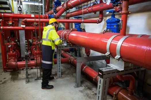
Steam pressure sets the body rating, flange class, and material; common industrial process steam runs from 30 psig heating mains up to 600 psig and beyond for chemical and refinery headers, and the separator body, gasket class, and connection standard must match that rating [S3]. Steam flow rate, expressed in lb/hr or kg/hr, sets the vessel diameter: too small a vessel forces velocity high enough to re-entrain the very droplets the device is trying to remove, and too large a vessel wastes insulation, drain, and capital cost [S1].
Allowable pressure drop is the second key sizing knob, because each separator type has a characteristic ΔP curve against face velocity, and pairing a flow meter immediately downstream of a high-ΔP separator will bias the meter reading. For most process lines the practical ceiling on separator pressure drop sits in the 0.2 to 0.5 bar range, and any tighter constraint pushes the design toward a larger vessel rather than a different mechanism [S1].
Material, Connection, and Maintenance Choices
Carbon steel (ASTM A105) covers most low-to-medium pressure steam service, while stainless steel (ASTM A240 304L) is specified for clean steam, food, and pharmaceutical lines, and for outdoor tracer duty where corrosion and freeze-thaw shorten cast iron life by a factor of 3 to 4 [S3]. Connection style follows pipe size and pressure: threaded NPT or BSPT for 1/2″ to 2″ lines, socket-weld for higher pressure, and flanged for sizes above 2″ or anywhere the vessel must be removed for cleaning without cutting the line [S3].
Maintenance access is part of the spec, not an afterthought, because knit-mesh pads foul, cyclones erode, and baffles collect sludge, and a separator without a removable head or a side-entry access turns a 2 hour pad swap into a full pipe cut. Drain leg sizing and the downstream steam trap selection must also be done together with the separator: undersize the drain and the vessel floods, which destroys separation efficiency and can push condensate into the steam header.
Who Should and Should Not Pick the Standard Baffle Separator

It is the wrong call for turbine admission lines, pharmaceutical clean steam, or any service where moisture must be held below 0.5% by weight, because the droplet cut size of a plain baffle is too coarse for those targets [S2].
Cyclonic and mesh units also lose to baffles in two specific cases: on very low-velocity steam, where centrifugal force collapses and the mesh pads see no flow differential, and on superheated steam, where the real moisture problem is pressure desuperheating, not entrained droplets, and a separator solves the wrong problem entirely [S1].
Pairing a Separator with Downstream Equipment
The separator protects three categories of downstream hardware, and the right pick depends on which one dominates the line. Control valves and pressure transmitters suffer seat erosion and calibration drift from droplet impingement, so a cyclonic separator immediately upstream of a tight shut-off industrial valve is standard practice on chemical and refinery headers. [S2]
Heat exchangers, turbine inlets, and clean-steam users need higher dryness, and a two-stage separator (cyclonic primary plus mesh secondary) or a dedicated cyclone separator sized for the line is the working answer [S2]. For applications where dissolved solids and liquid contamination ride with the condensate, a true steam separator staged ahead of a clean-steam generator or a humidification chamber keeps carryover out of the product stream.
Quick Selection Logic
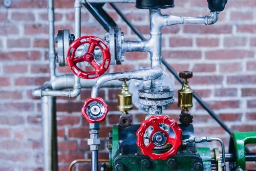
Start with the six inputs above, then pick the mechanism by droplet size and target dryness, then size the vessel by flow and allowable ΔP, then match the body material and connection to pressure and service, and only then specify the drain leg and the steam trap. A spec sheet that lists pressure, flow, pipe size, temperature, inlet moisture, and target outlet dryness in that order will get a clean quotation on the first round; a sheet that lists only line size and "remove moisture" will spend two cycles on clarification. [S1]
Track next: any 2026 update to ASME B31.1 power-piping guidance on separator placement at pressure-reducing stations, and any factory-published dryness-vs-velocity curves for cyclonic and mesh units, which are the two specs that drive real vessel diameter in most process plants [S1][S2].
Background reading: Warehouse Waterproofing Membrane Selection: Material, Build and Seam Spec Map.