
A steam separator installed in a horizontal pipe run, immediately upstream of a control valve and ahead of a 0.020 in. perforated stainless-steel strainer, is the standard arrangement for removing carryover condensate before it can erode the valve trim or trigger waterhammer on reopening [S3][S2].
The practice applies to modulating steam control valves, pressure-reducing valves (PRVs), and on/off steam valves; the separator works together with a drip pocket and a properly sized steam trap so condensate is collected and discharged at controlled intervals rather than swept into the valve body [S2][S6].
Why Upstream of the Control Valve, and What the Separator Actually Does
A steam separator's job is mechanical, not thermostatic: it uses centrifugal, baffle, or vane action to throw denser water droplets out of the steam flow so only dry steam continues downstream toward the actuator [S5]. Steam leaving a boiler or header can carry 1-3% moisture by mass, and once that moisture reaches a throttling valve it flashes across the trim, erodes the seat, and destroys the Class IV or V shutoff classification that a properly specified steam control valve is supposed to hold [S3].
Installing the separator upstream rather than downstream is non-negotiable for two reasons. First, condensate reaches the valve in the inlet direction, so the separation has to happen before the valve, not after. Second, when a steam control valve has been closed for any length of time, the upstream line cools and condensate pools in the horizontal pipe; on reopening, that slug accelerates into the valve cavity and produces a waterhammer shock that cracks bonnets and shears stems [S2]. A separator with a drip pocket and a steam trap upstream of the valve breaks that slug into a managed, continuous discharge before the valve opens [S3][S6].
Orientation, Pipe Run, and Mechanical Layout
Steam control valves are specified to be installed in horizontal pipework with the spindle vertical, and a control valve installed in a vertical line has no ability to self-drain, which is why installation manuals call the horizontal-with-upright-actuator configuration the only acceptable geometry [S2][S3]. Within that horizontal run, the steam separator sits on the upstream side, followed by a drip pocket and a strainer, with the control valve immediately downstream of the strainer [S2][S3].
Three layout details decide whether the arrangement actually works. (1) The separator body must sit in a horizontal pipe section with its internal baffles or cyclone vanes aligned to the horizontal flow, not pitched or inverted. (2) The strainer basket should be installed with its segment horizontal, never pointing down, so condensate does not pool in the basket and pass through the valve during the next demand pulse [S3]. (3) A 3 ft (about 1 m) straight pipe run on each side of the control valve is the typical minimum to keep the flow profile uniform before the actuator trim sees it, which is a layout rule that the same upstream separator arrangement inherits [S4].
Comparison: Cyclone, Baffle, and Inline Coalescer Separators for Control-Valve Service
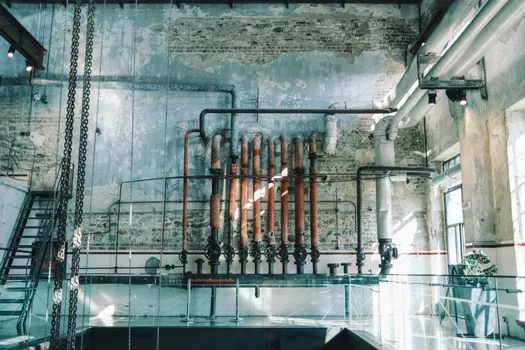
Three separator styles are regularly specified upstream of steam control valves, and they line up against the criteria that matter for valve protection: moisture-removal efficiency, pressure drop, footprint, and sensitivity to orientation. [S1]
Cyclone separators (also called centrifugal separators) spin the steam inside a tangential body so droplets are flung outward and fall into an integral drain pocket; they deliver the highest single-pass moisture removal, are the most sensitive to vertical installation because gravity is what moves the collected water to the drain, and are the largest of the three options [S5]. Baffle-style separators use a series of angled plates or mesh pads and are the cheapest, the most tolerant of slight misalignment, and the worst performers at high velocity because re-entrainment rises above roughly 30 m/s. Inline coalescer packs, often stainless-steel mesh, give the lowest pressure drop at low to moderate flow and are commonly used when the upstream header is already relatively dry, but they are the most sensitive to fouling and need a strainer ahead of them, not after.
For most steam control-valve service where the line size is 2 in. or larger and the velocity is moderate, a cyclone separator with an integral trap is the default choice because the moisture removal is consistent and the drain path is built in, which removes one of the failure modes a separate drip pocket would otherwise introduce [S5].
Drain, Trap, and Strainer: The Three Components That Make the Separator Work
A separator with no working drain is just a piece of pipe; a strainer with no blow-down is a debris reservoir. The Fisher steam conditioning installation guide recommends drains both upstream and downstream of the steam conditioning valve wherever condensation or incomplete evaporation is possible, and Spirax Sarco's commissioning module repeats the same logic for any control valve in a steam line [S1][S2]. The reason is straightforward: condensate forms in the line any time the line is below saturation, which includes every startup, every shutdown, and every low-load period.
The drain components that complete the upstream train are: (1) a drip pocket, sized to the line diameter and located at the lowest point of the horizontal run immediately ahead of the separator, so condensate collects by gravity rather than by flow turbulence [S3]; (2) a steam trap on the drip pocket, sized so that the condensate is removed rapidly, even when the steam pressure in the downstream equipment is at its minimum, so the pocket does not back up and overflow into the valve [S6]; and (3) a 0.020 in. perforated stainless-steel strainer with the basket segment horizontal, mounted downstream of the separator and immediately ahead of the control valve, to catch scale and pipe-thread debris that the separator cannot remove [S3]. This three-component train is the standard arrangement taught in vendor best-practice documents, and skipping any one of the three is the usual root cause of premature steam control-valve failure [S3][S4].
Failure Modes When the Upstream Separator Is Wrong or Missing
The four most common failure modes on steam control valves trace directly back to the upstream separator train, and each one has a recognizable symptom that points to a specific missing component. [S1]
Symptom: wire-drawn seat and seat leakage rising from Class IV to Class V or worse within months of commissioning. Root cause: wet steam reaching the trim, almost always because the separator is undersized, the line is running above its design velocity, or there is no separator at all [S3]. Corrective action: install a cyclone separator rated for the actual line flow, with the integral trap in working order; replace the valve trim if leakage has already crossed the FCI 70-2 class boundary [S3].
Symptom: bonnet crack or stem shear on first reopen after a weekend shutdown. Root cause: waterhammer from a slug of condensate that pooled upstream of the closed valve, which a drip pocket and trap combination would have drained during the idle period [S2]. Corrective action: add a drip pocket at the lowest point of the upstream horizontal run and a steam trap sized for the start-up condensate load; do not rely on the separator alone, because the separator removes entrained moisture, it does not drain a static pool [S2][S6].
Symptom: valve sticking or hunting within a few hundred hours of startup. Root cause: scale or thread-sealant chips lodged in the cage or seat, almost always because the strainer is missing, the wrong mesh size is specified, or the strainer basket was installed with the segment pointing down so it fills with condensate and chokes [S3][S4]. Corrective action: fit a 0.020 in. perforated stainless-steel strainer with the basket segment horizontal, and add a routine blow-down to the maintenance plan so the basket does not slowly blind off.
Symptom: actuator unable to stroke fully at high demand. Root cause: insufficient inlet pressure at the valve, frequently because the strainer is partially blinded or the line strainer upstream of the separator is missing, which lets debris load the separator and the second strainer in series [S3]. Corrective action: walk the upstream train in order, separator then strainer then valve, and check each one for pressure drop against the design delta-P; replace any component whose measured drop is more than roughly twice the clean value.
Standards, Sourcing, and What to Specify on a P&ID
The most commonly cited reference points for the upstream separator arrangement are vendor installation guides, including Fisher (Emerson) document D102304X012 for steam conditioning valves, Spirax Sarco Module 5.5 for general control-valve installation and commissioning, and the Inveno Engineering best-practice note on steam control-valve installation [S1][S2][S3]. FCI 70-2 is the standard that defines the six internal leak-rate classes (I through VI) used to specify seat tightness on a steam control valve, and Class IV is the typical minimum for general steam service, with Class V or VI required where tight shutoff matters to the process [S3].
On a P&ID, the upstream separator train reads as: steam header, drip pocket with steam trap, cyclone or baffle separator, 0.020 in. perforated stainless-steel line strainer, then the control valve, then any downstream drip pocket and trap if the line continues to a PRV or heat-exchanger coil [S3][S4]. When the geometry forces a vertical run, a separator should not be specified to do the work of a drip pocket; the upstream pipe should be re-routed to a horizontal section, or a drip leg installed at the base of the riser, because a separator has no drain capacity for a static column of condensate [S2]. Where the service is gas rather than steam, the same upstream separator arrangement is replaced by a particulate filter and the same horizontal-pipe, vertical-spindle rule applies [S4].
For deeper background on the equipment family, the encyclopedia entries on steam separators, steam traps, and control valves cover the design and selection basis that this installation rule depends on. Trackable signals for the next review cycle: any revision to FCI 70-2 leakage-class definitions, and any vendor update to inlet-pipe-length tables for steam service above 100 psig, both of which would shift the 3 ft straight-run and 0.020 in. strainer values cited here.
This topic is covered further in Read a Truck Crane Load Chart: Capacity Versus Radius.