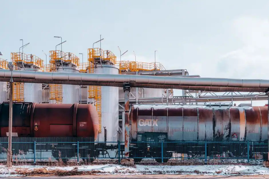
Oil and gas steam-trap selection starts with application duty: condensate load, operating and back pressure, temperature, air venting, installation orientation, and the need to prevent water hammer.
The final model must fit its specific service rather than rely on a generic pressure rating. Common duties include steam-main drainage, heat-exchanger condensate removal, tracer heating, and turbine drainage, each with different load and discharge requirements [S2][S5].
Steam Trap Duties and Operating Boundaries
A steam trap must hold back steam while allowing condensate, air, and other non-condensable gases to discharge. These functions apply to steam distribution piping, process heating equipment, tracer lines, and turbine or other drive-steam equipment [S1][S2][S8].
For steam-main drainage, the trap should remove condensate promptly and minimize pooling, because condensate left in a high-velocity steam path can produce water hammer. Steam-trap selection should account for the required pressure, condensate load, and air-venting performance, as well as system-design and maintenance needs.
For process heat exchangers, a continuously discharging type is generally preferred so that condensate does not flood the heating surface, reduce heat transfer, or make heating uneven. An air-venting function is also useful where start-up air remains trapped after steam condensation [S2]. Crude-oil heating is a representative application because steam reduces the oil viscosity while its latent heat is transferred to the product [S5].
Selection Procedure from Duty to Purchase Order
A disciplined selection process uses four steps: identify the required discharge behavior, select a compatible trap technology and model, calculate the condensate load with the manufacturer’s safety factor, and compare candidates on life-cycle cost [S2].
Start with the service category and required discharge condition, including hot or subcooled discharge. Then establish inlet pressure, outlet or back pressure, operating temperature, condensate load, air handling, orientation, and installation environment [S2][S7]. Compare the model’s pressure and temperature ratings against the operating envelope, not merely against the boiler or utility-header rating.
These values illustrate the required inputs: a trap cannot be selected correctly from condensate load alone.
After calculating load and applying the manufacturer’s recommended safety factor, compare installed and operating costs rather than purchase price alone. A low-cost trap that leaks live steam, sticks in service, or causes water hammer can have a poor life-cycle result [S2][S4].
Thermodynamic, Thermostatic, and Mechanical Trap Types
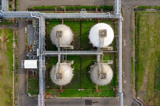
Thermodynamic, thermostatic, and mechanical traps satisfy different combinations of discharge temperature, load variability, air handling, pressure, and installation requirements. Their selection should follow the application, because no single technology covers every oil and gas steam duty [S4][S6].
Emerson identifies mechanical, thermodynamic, and thermostatic steam-trap technologies and lists bellows, balanced-pressure, bimetallic, disc, piston, lever, float, and bucket types. These are screening ranges, not complete model specifications.
A trap selected only for its pressure rating can still be unsuitable if its discharge temperature, capacity, connection, or installation orientation conflicts with that duty.
Pressure, Capacity, Back Pressure, and Temperature
Trap selection must satisfy pressure ratings, discharge capacity, differential pressure, and temperature rating. Emerson identifies pressure ratings, differential pressure, and condensate load as primary sizing factors, with material and air handling among the secondary factors [S4].
Back-pressure sensitivity is particularly important where discharge enters a pressurized condensate header. A thermostatic trap can lose discharge force as the available differential pressure falls, while a mechanical trap has its own sensitivity to operating pressure and differential pressure. The manufacturer’s capacity tables must therefore be evaluated at the actual inlet pressure, outlet pressure, and corresponding steam or condensate temperature.
Temperature limits apply to the trap body, seat or disc, sensing element, and sealing arrangement, not only to the steam line. For oil and gas service, also verify the selected body material against condensate chemistry, treatment chemicals, and the installed environment [S2][S7]. A pressure- and temperature-rated carbon steel trap can still be a poor choice where sour condensate, chlorides, erosion, or freezing are relevant.
Do not use a nominal trap size as proof of capacity. Confirm the rated condensate load at the actual differential pressure, then apply the manufacturer’s stated sizing margin. Also verify whether discharge is to a gravity return, a pressurized header, or a raised line because those layouts change the required discharge behavior [S1][S2].
Water Hammer, Lift, and Condensate-System Limitations
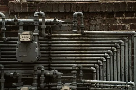
Persistent water hammer on an established system is more likely to indicate a piping or layout defect than a defective trap. Causes include failure to remove condensate from high-velocity steam lines, a temperature-controlled application where condensate must be lifted, an undersized return line, flooding, or flash-steam throttling [S1].
Where condensate must lift after the trap, a tendency toward water hammer remains even when the trap type is correct. The arrangement may require a condensate pump, a pump-trap arrangement, or another drainage device. When steam demand falls below the return-header back pressure, condensate flow can stall, and a combination pump and trap using a higher secondary pressure may be required [S1][S2].
Steam mains should be drained at 30–50 m intervals using adequately sized drain pockets, and every riser bottom should be drained [S1]. Installers must also check whether the return pipe can accept the calculated load. A trap cannot correct an undersized line, flooding header, or unsuitable elevation.
Failure modes include leakage of live steam, water hammer, impingement, corrosion, freezing, and loss of air-venting capability. Failed traps may release condensate onto walkways, and live-steam loss raises steam-generation demand and emissions [S4]. The steam trap is one part of the condensate system, not a substitute for sound piping design.
Installation Environment, Dirt, and Materials
Steam traps installed in oil and gas facilities must be checked for orientation limits, dirt sensitivity, resistance to freeze damage, ease of maintenance, back-pressure behavior, and air-venting requirements [S4]. These checks can remove a technically capable trap before field installation begins.
Dirt matters because condensate can carry traces of boiler-feed treatment products, while pipeline drainage can introduce contamination. A mechanical float or bucket design may be sensitive to dirt, whereas a sealed thermostatic or thermodynamic element can have different contamination and wear behavior [S1]. Inspection access, strainer arrangements, spare-part strategy, and the ability to isolate a trap should be considered for remote or hazardous installations.
For outdoor or cold-service applications, confirm freeze protection and the permitted installation orientation. The Emerson guide treats freeze resistance and orientation limits as explicit selection factors, rather than installation details [S4]. Check the manufacturer’s drawing for whether the unit must be upright, inverted, angled, or installed in a specific discharge orientation.
Body and trim materials should be checked against steam pressure and temperature ratings, condensate composition, and external corrosion exposure. The procurement specification should identify the body material, wetted material grade, end connection, pressure class, and any project-specific corrosion requirement, rather than writing only “steam trap, carbon steel.” [S2][S7]
Oil and Gas Service Suitability and Final Shortlist
A mainstream low-pressure drip trap is not appropriate for every oil and gas application. It is generally unsuitable for a high-capacity heat exchanger with fluctuating condensate load, a raised condensate installation, a high-back-pressure return, or a duty requiring strong air venting [S2][S4].
Use the following shortlist logic. Choose a thermodynamic trap for a steam header drip or tracing duty where rapid, near-steam-temperature discharge and high air tolerance are priorities. Consider thermostatic traps for process heating where controlled discharge temperature and air removal matter. Consider mechanical float, bucket, or lever traps for larger or fluctuating process loads when the installation can provide clean service conditions and suitable differential pressure [S4][S6].
For each shortlisted model, verify operating and design pressure, design and operating temperature, capacity at the actual differential pressure, connection type, body and trim materials, orientation, air handling, back-pressure or stall behavior, and maintenance access. Also compare life-cycle cost and availability of spare parts [S2][S4].
Record the calculated condensate load, safety factor, inlet and outlet pressures, temperatures, installation orientation, return-line elevation, condensate chemistry, and air-venting requirement on the datasheet request. A model-specific oil and gas data sheet can then be checked against the application without relying on generic trap nomenclature [S1][S2][S4].
Before purchase approval, check the finished steam-trap specification against the pipeline arrangement. If the service involves crude heating, water hammer, tracer freezing, or a pressurized condensate return, compare the trap with the wider steam trap selection for pulp and paper plants reference to identify which failure-mode checks transfer across process industries.