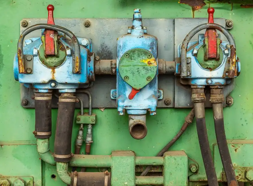
Size an oil and gas balancing valve from the calculated design flow, not the pipe diameter, and verify its pressure drop at minimum, normal, and maximum operating conditions [S3].
Manual fixed-orifice, variable-orifice, and automatic balancing valves cover different duties from commissioning through continuous flow control in pipelines, manifolds, and multi-branch equipment.
Define the balancing duty before choosing a valve
A balancing valve regulates flow and pressure to distribute the required flow among branches, risers, or parallel rows. Multi-row installations are the core application because unequal resistance can cause one branch to receive more flow than intended [S4][S5].
The design basis is a measurable flow target for every branch, not simply the available line size. In the documented heating-water system with 100 coils, 65 ¾-inch valves were preset to dial position 1.0 while the remaining 35 valves, ranging from ¾ inch to 2½ inches, were set fully open.
For oil and gas systems, establish the fluid composition, normal and design flow, available pressure, allowable pressure drop, branch configuration, and required control mode before requesting a valve. Gas flow is compressible, so a water-based flow curve is not acceptable without conversion to the applicable gas basis. The selected balancing valve must also meet the specified material, sealing, temperature, and pressure requirements.
Compare fixed, variable, and automatic balancing valves
Fixed-orifice valves offer repeatable restriction and a simple commissioning method, but they cannot compensate for changing system resistance. Variable-orifice valves provide a wider adjustment range, while automatic valves can track a controlled flow or differential pressure as operating conditions change. [S2]
For a fixed-orifice valve, flow is calculated from Q = Cv√ΔP, where Q is flow, Cv is the flow coefficient, and ΔP is pressure drop across the measuring ports [S2].
Variable-orifice valves require a different calculation because Cv changes with knob position.
Apply a flow-based selection method
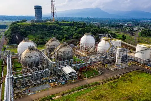
Calculate each branch’s required design flow, identify the controlling pressure condition, and select the valve from its flow and pressure-drop performance rather than from nominal pipe size.
Use nominal flow as the primary valve-sizing point, not a broad minimum-to-maximum range. In the documented installation, terminal unit reheat coils with a design pressure drop below 0.75 inches water column were preset to dial position 1.0 to prevent debris buildup that could block flow, while the remaining 35 valves, ranging from ¾ inch to 2½ inches, were set to the full-open position.
Verify available pressure at the valve under the intended pump or compressor condition. A balancing valve that cannot pass its nominal flow within the allowable differential pressure is unsuitable, even if its nominal size matches the branch. The valve should also avoid consuming more pressure than necessary where that would disturb downstream equipment, separator capacity, or burner operation.
For gas service, state whether the published performance is based on standard or corrected volume, and whether the correction uses the specified reference pressure and temperature. Require the manufacturer to supply the applicable flow coefficient, correction method, and test medium. A Cv quoted only for liquid service cannot be transferred directly to a hydrocarbon gas calculation.
Choose actuation for the operating strategy
Manual balancing is appropriate when the required flow is stable, commissioning access is available, and downstream demand is predictable. The adjustment is static after setting, and two pressure-test ports allow the differential pressure across the internal restriction to be measured and converted to flow [S2].
Variable-orifice manual valves are the practical choice when the commissioning range is wide or the final setting is uncertain. The measured differential pressure must still be interpreted against a curve for the actual valve size and knob position because Cv is not constant [S2].
Automatic balancing suits systems whose branch demand changes during operation or where continuous flow control is required. The automatic recirculation valve is a related control concept, but an automatic balancing valve remains a flow-balancing device rather than a general pressure-control substitute. Specify whether it modulates flow, differential pressure, or a remote set point.
Do not select the mainstream manual valve for a continuously changing process network, a critical service with no permissible flow deviation, or a duty requiring remote set-point adjustment. Its static opening cannot correct pressure-driven flow changes after commissioning. Conversely, automatic balancing is unnecessary where a fixed branch has one stable design flow and field adjustment is acceptable.
Set materials, sealing, and pressure-temperature limits
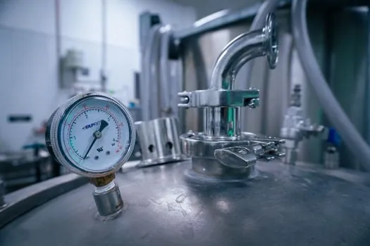
Balancing-valve body, trim, stem, seat, and seal materials must be compatible with the hydrocarbon or gas mixture, including water, sulfur compounds, aromatics, and other constituents identified in the service analysis. The research material defines balancing-valve functions and sizing principles but does not establish a universal material grade for oil and gas service, so material selection must follow the specified fluid and project design basis. [S3]
For hydrocarbon liquid service, verify the valve’s qualified pressure-temperature rating and closure capability at the lowest expected temperature. For gas service, confirm that the valve is rated for the design pressure, maximum allowable pressure, and minimum and maximum operating temperature rather than relying on a nominal line-size designation.
Check whether the differential-pressure measuring ports are isolated and whether their arrangement affects leakage or debris accumulation. Any installed strainer, filter, or separator upstream can alter pressure loss and flow distribution, so its pressure-drop curve must be included in the hydraulic calculation.
Valve trim and seals also require a documented exclusion or suitability decision for the project fluid. Where hydrocarbon compatibility data are missing from the submittal, request test data or a manufacturer approval rather than assuming carbon steel, stainless steel, or an elastomer seal is universally acceptable.
Specify commissioning and field verification
Commissioning should start with pump or compressor shutoff head confirmed against the equipment curve, followed by total system flow measurement and branch-by-branch adjustment. In the 100-coil example, the initial readout was compared with pump flow before the valves closest to the pumping system and carrying more than design flow were throttled [S3].
For each branch, record valve size, valve setting, upstream and downstream pressure, differential pressure, calculated or measured flow, and deviation from the target. For fixed and variable manual valves, use a differential-pressure instrument across the manufacturer’s designated ports and apply the published valve curve rather than a generic instrument conversion [S2].
Acceptance tolerances should be stated in the project documents. The research establishes the method and example settings but does not provide a universal tolerance, so do not invent a percentage. The project specification should define the acceptable band for flow or differential pressure and the procedure for correcting noncompliant branches.
For multi-row gas equipment, verify that the balancing test medium matches the operating medium or that the correction is validated. A valve adjusted successfully with air or nitrogen may not produce the same indicated gas flow at high pressure unless the manufacturer’s correction basis has been applied.
Build a procurement-ready shortlist
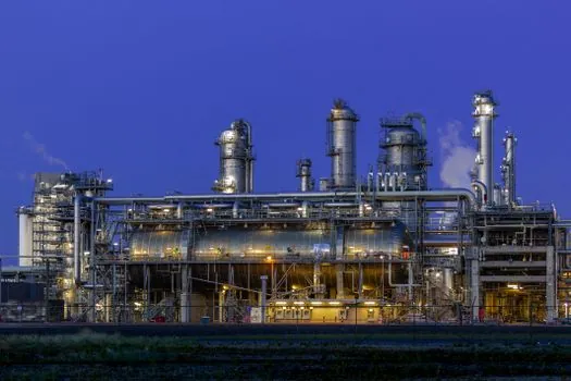
Shortlist the manual fixed-orifice, variable-orifice, and automatic options against four criteria: required flow range, allowable differential pressure, operating-fluid qualification, and commissioning strategy. A fixed-orifice unit fits a stable branch with a defined flow and verified Cv; a variable-orifice unit fits adjustable commissioning; an automatic unit fits changing demand with continuous control. [S2]
Before purchase, require the datasheet to state valve size, relevant flow range, Cv or equivalent gas-performance data, allowable pressure and temperature, body and trim materials, seal material, end connection, actuator or adjustment method, differential-pressure ports, and certified product designation where the application requires certification. Available manual product families include Victaulic Series 78BV, 790V, 786V, and 78KV, but the model number does not replace duty-based sizing [S7].
Use the oil and gas control valve selection guide when the balancing device also performs active process throttling. Its selection basis differs from a dedicated balancing valve, whose primary purpose is to limit each branch or riser to the flow required by the terminal design [S6].
The final purchase order should identify the calculated nominal flow, minimum and maximum design flows, applicable fluid basis, allowable pressure drop, operating pressure and temperature, materials, and required test or certification documents. That shortlist prevents the most common procurement error: buying a valve whose nominal bore matches the pipe while its internal flow capacity does not match the process duty [S3].