
Desalination steam-trap selection should start with the calculated condensate load, operating pressure, temperature, back pressure, air-removal duty, and installation orientation, then apply the manufacturer capacity margin [S1][S2][S4].
Thermal and mechanical desalination units use steam for heating, process generation, or equipment tracing, but seawater chemistry, blowdown, and frequent cycling make body material, corrosion resistance, maintenance access, and failure behavior decisive criteria [S2][S4].
Define the Steam-Trapping Duty
A steam trap must discharge condensate and air while retaining live steam, so neither discharge capacity nor pressure rating alone defines a suitable device [S1][S5]. For each heater, exchanger, steam header, or tracer line, record the design pressure, design temperature, operating inlet pressure, outlet or back pressure, startup air load, and expected condensate rate [S2][S4].
Emerson classifies mechanical traps as using the density difference between steam and water and identifies float and bucket designs as common types; thermostatic traps operate on the temperature difference between steam and condensate and include bellows, balanced-pressure, and bimetallic designs; and thermodynamic traps use heat energy in hot condensate and kinetic energy in steam to open and close, with disc, piston, and lever types [S4]. Each must be matched to the installation rather than selected only by nominal size.
For example, These bands are selection guides, not universal pressure ratings for an individual trap.
Compare Trap Types Against Four Criteria
Mechanical traps are suited to substantial or fluctuating process condensate loads and generally provide useful air-handling capacity, while thermodynamic traps are compact and robust for drip legs, tracing, and high-pressure service [S4][S5]. Thermostatic traps discharge condensate close to steam temperature and are commonly preferred where rapid drainage and reduced subcooling are important [S2][S5].
For a steam-heated desalination heat exchanger, continuous condensate discharge and startup air venting usually favor a thermostatic or properly selected mechanical device [S2].
Size the Condensate Load, Not the Pipe
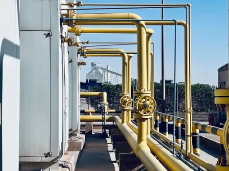
The trap model must be selected from the operating condensate load and then checked against the manufacturer’s capacity curve at the actual inlet pressure, outlet pressure, and steam temperature, with the manufacturer’s safety factor applied [S2].
Desalination equipment can impose several simultaneous loads: heater drains, steam-header drains, sample-line drains, tracing points, and condensate recovery from flashed steam. Each location needs a separate load case because combining them into one theoretical trap can conceal poor distribution and leave individual points unprotected [S1][S4].
The discharge pressure is equally important. A trap selected only from inlet pressure can lack capacity when the return system has elevated back pressure.
Match Materials to Seawater and Steam Conditions
Trap body material must be selected from the maximum operating temperature and pressure, but desalination service also requires evaluation of the chemical environment around the trap, including saline carryover, corrosion products, and treatment chemicals [S2][S6]. Stainless steel, bronze, duplex stainless steel, and nickel alloys have different exposure to chloride-bearing environments, and no alloy should be selected from a generic seawater label alone [S2][S4].
Temperature rating, pressure rating, body material, and internal materials must be checked as one envelope. Emerson identifies temperature and pressure ratings as primary sizing factors and material as a secondary factor, while TLV places pressure rating, temperature rating, discharge capacity, trap type, and body material among the principal selection considerations [S2][S4].
External corrosion is not the only concern. Condensate chemistry, solids from boiler treatment, salt contamination, and scale can restrict or damage internal passages. Dirt sensitivity therefore belongs in the technical comparison, alongside back-pressure sensitivity, freeze resistance, orientation limits, and air-venting performance [S4].
Control Water Hammer and Backpressure

Water hammer can result from failed condensate removal, an undersized or flooded return line, overpressurization with flash steam, unsuitable trap selection, or a leaking trap [S1]. In an established installation, repeated water hammer failures should first prompt review of the pipe layout, trap position, lift condition, and return-line capacity rather than automatic replacement with a larger trap [S1].
These are layout controls that complement, rather than replace, trap selection.
Where heated equipment has condensate lift after the trap, water hammer remains a system risk. The installation may need a pump-assisted trap or another pumped drainage arrangement instead of a gravity-discharge trap [S1][S2]. On a steam main, consider the broader arrangement of steam separators, air release valves, and steam ejectors before assigning every gas-removal function to the local trap.
Match Orientation, Maintenance, and Failure Risk
Installation position, permitted orientation, connection type, and available maintenance space are mandatory checks because a correctly rated trap can still fail or operate poorly when installed incorrectly [S1][S4]. Emerson’s selection factors include orientation limits, air venting, connection type, integrated strainer, spare parts, painting, and documentation [S4].
Steam traps are commonly tested only once or twice per year, and a failed trap may remain undetected for more than 6 months [S4]. In a desalination plant, that interval makes an inspection strategy as important as initial selection. Specify access for testing, isolation, basket or screen removal, and replacement without disturbing critical production equipment.
Failure consequences must be assigned by location. A failed heater drain can reduce heat transfer and retain condensate, while a failed trap discharging live steam can increase steam consumption, noise, and safety exposure [S4][S5]. For redundant steam-heated units, verify whether isolation and alternate drainage are available before accepting a single-trap arrangement.
Apply a Controlled Selection Workflow
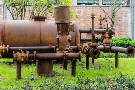
Use a four-step record: identify the discharge requirement and matching trap type; select a model for pressure, temperature, orientation, and installation conditions; calculate the load and apply the manufacturer’s safety factor; then confirm the lowest life-cycle cost among compliant options [S2]. This keeps low purchase price from overriding condensate capacity, reliability, or maintenance exposure.
For desalination, the shortlist logic is straightforward. Use a robust thermodynamic arrangement for small high-pressure or isolated drip duties, a thermostatic trap where near-prompt drainage is required, and a mechanical trap where process condensate flow is medium, large, or fluctuating and air removal is significant [S2][S4]. Exclude any candidate that lacks a verified capacity point at actual pressure and temperature, compatible body material, correct orientation approval, and a practical maintenance route.
Do not use a standard steam-trap catalogue rating as a substitute for the plant heat balance. Confirm each drain point, calculate peak and startup loads, establish allowable back pressure, identify seawater or chemical exposure, and obtain the selected manufacturer’s sizing curve and installation instructions. The steam trap specification is complete only when those fields and the failure-response plan are documented together.