Steel fiber reinforced concrete (SFRC) relies on a tight 20-50 kg/m³ dosage band, a 30-50 mm hooked-end length, and an aspect ratio of 50-80 to convert brittle concrete into a post-crack ductile material [S2].
The product itself is a cold-drawn low-carbon or stainless wire deformed and cut to length, with typical 1.0 mm diameter and ≥650-850 MPa tensile strength per YB/T151-1999 and JG/T3064-1999 [S2]. This guide walks through the field sequence — subgrade, dosing, mixing, placement, finishing, and acceptance — that turns a bagged fiber into a structural layer, drawing on current-daye, Suzhou Yujian, and Harde product data published 2026 [S3][S4].
Fiber Types and Geometry That Drive the Mix
Hooked-end cold-drawn low-carbon wire is the default for industrial floors and jointless slabs, while micro-steel fiber (0.2-0.3 mm diameter, 10-20 mm length) is the default for UHPC and shotcrete overlays [S2][S4]. Stainless 304/316 fibers, 25-35 mm long and 0.3-0.7 mm in diameter at ≥650 MPa, are specified for chemical-plant bases and coastal structures where carbon-steel would corrode and stain [S2].
Avoid round straight fibers and melt-extracted fibers: their smooth cylindrical surface and oxide skin, respectively, drop bond strength below what the design assumes [S6]. For context on why fiber choice sits inside a wider concrete reinforcement decision tree, the engineering trade-off is between ductility (hooked), tensile pull-out capacity (indented), and corrosion tolerance (stainless) at a unit cost step of roughly 3-5× from carbon to stainless [S2].
Dosage Calculation and Aspect-Ratio Check
Most industrial-floor and tunnel-segmental-lining designs sit in a 20-50 kg/m³ dosage band; UHPC climbs to 80-160 kg/m³ with micro-fiber and 6-12 mm straight steel or stainless [S4]. Aspect ratio (length ÷ equivalent diameter) is the single number that controls crack-bridging efficiency: 50-80 covers most slab and pavement work, while UHPC and shotcrete target 100-200 on micro-fiber [S2][S4].
Round straight fibers and melt-extracted fibers should be excluded on bond-strength grounds, with surface oxide and round cross-sections reducing pull-out resistance enough to be disqualified in modern practice [S6]. Converting steel fiber selection into a mix design also means checking the supplier's mill certificate against YB/T151-1999 or EN 14889-1, and confirming tensile strength tolerance (±5% per the Harde data sheet) and equivalent-diameter tolerance (±0.03 mm) on the lot certificate [S2].
Subgrade Prep, Formwork, and Joint Layout
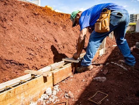
Subgrade must be moist, compacted to ≥95% modified Proctor, and free of standing water before the SFRC pour; pumping water through fresh fiber-reinforced paste washes cement off the fiber surface and creates a laitance-prone surface crust [S3]. Formwork should be tight: SFRC at 30-50 kg/m³ will pass a 10 mm construction-joint gap and bleed cement through a 5 mm seam that plain concrete would block. Saw-cut joints are typically laid at 4-6 m centers for 120-180 mm slabs, with the cut window 6-18 hours after finishing depending on ambient temperature.
Rebar and any embedded parts should be chaired and tied before the first fiber goes in, because fiber addition makes the mix stiffer and harder to work around protruding rebar after the fact. If the slab is composite with structural steel, the installation tolerances for embedded plate and stud must already be set — fiber does not absorb misalignment.
Mixing Sequence, Addition Rate, and Balling Prevention
The single most common field failure is fiber balling: a clump of unwetted fibers wrapped around the mixer paddles that never breaks down. It happens when fibers are dumped onto dry aggregate, when a high dose of long hooked-end fiber is added at once, or when the mixer is a low-shear drum unsuitable for fibrous mixes. The fix is a two-stage addition: load aggregate, cement, and 60-70% of mix water first, mix 30 seconds to wet out the fines, then meter fiber onto the conveyor or through a pre-wetting screen at ≤60 kg/min into the running mixer [S3].
Total wet-mix time after fiber addition is 90-150 seconds at mixer rpm rated for the rated capacity; under-mixing leaves bundles, over-mixing fatigues the hooked ends and reduces pull-out capacity. The 38 mm × 1.0 mm × 850 MPa hooked-end fiber from Harde disperses cleanly at 25-35 kg/m³ in a 1.0 m³ pan mixer, but a 50 mm × 1.0 mm fiber at 60 kg/m³ in a 9 m³ drum truck has been documented to ball unless fed through a vibratory spreader at the truck chute [S2][S3]. Adding fibers in a pre-blended loose state at 20 kg paper-bag or 1,000 kg bulk-bag packaging allows dosing by weight, and avoids the bag-tear clumping seen when 25 kg bags are ripped open in one motion [S2].
Placement, Vibration, and Finishing
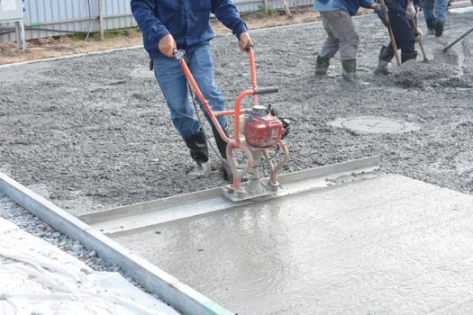
Place SFRC in lifts no deeper than 200 mm and vibrate with a 50-60 mm poker or vibrating screed immediately after the lift — do not let a layer of fibers float to the surface and another settle at the bottom of the lift, because that segregation is irreversible once initial set starts. Strike off with a vibrating screed running 2-3 m/min; hand-screeding SFRC at 30 kg/m³+ is slow and gives a fiber-rich surface that spalls under forklift traffic.
Floating must wait for the bleed water to disappear, the same window as plain concrete; power-troweling too early closes the surface and traps bleed water, leaving a weak laitance layer that peels under traffic. For UHPC and high-dosage micro-fiber, internal vibration is replaced by table vibration or form vibration at 8,000-12,000 rpm because the dense fiber network dampens poker energy [S4]. In tunnel segmental linings, the cast face is finished against a steel form; surface laitance is later hydro-blasted to expose fibers for the final architectural surface.
QC Tests, Acceptance Criteria, and Common Failures
Acceptance testing has two gates: fresh and hardened. On the fresh side, the only reliable balling check is to wash a 5 kg sample through a 5 mm screen and count unwetted bundles; a clean mix gives zero bundles over 50 mm across. Slump for SFRC at 30-50 kg/m³ should land 50-100 mm; a higher reading means the fiber content is low, a lower reading with stiff mix means water was added at the truck — both fail the dosage check. [S2]
Hardened acceptance follows EN 14889-1 or YB/T151-1999: cast six 100×100×400 mm beams per lot, test residual flexural strength at mid-span deflection of 0.5 mm and 3.5 mm. Typical acceptance is fR1 ≥ 4.0 MPa and fR3 ≥ 3.0 MPa for industrial-floor mixes; UHPC and tunnel segments push those numbers into the 8-20 MPa band with the same test method [S2][S4]. Common rejection causes: balls visible on the slab surface after power-trowel, edge spalling under traffic within 30 days, and flexural residual 20% below design at the 0.5 mm deflection point. When any of these surface, the slab is not repaired — it is cored, the dosage is verified against the batch ticket, and the affected panel is replaced down to the next joint.
Next signal to track: whether a project moves from carbon hooked-end to stainless micro-fiber in coastal plants, and whether the per-ton price gap narrows as Suzhou and Daye scale 10,000-100,000 t/yr capacity [S3][S4].
Spec-level background on the components involved: linear guide.