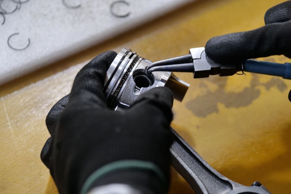
An embed is only as good as the bond it forms with the parent structure: the three-step install sequence (prep → set → verify) drives the published pull-out and shear values that show up on the submittal sheet, and skipping any step derates those numbers by 20-40%.
Embedded parts — anchor plates, lifting sockets, dovetail slots, threaded inserts, ferrule inserts — bridge poured-in-place concrete, structural steel, and machinery bases. Correct field installation protects against two failure modes that almost always show up in commissioning reports: spalled concrete around the embed, and mislocated inserts that force shimming under baseplates. Both are avoidable when the procedure is written to a tolerance, not a vibe.
Pre-Install: Surface, Geometry, and Document Check
ACI 318-19 Chapter 17 governs cast-in-place and post-installed anchorage in concrete; on a well-run site the embed submittal is checked against that chapter before any rebar is tied, not after the pour [S1] (2011-05).
Before the first anchor goes in, the crew confirms four items in writing: the embed drawing revision (stamped by the EOR), the material cert (mill cert or MTR), the parent-surface prep method (SSPC-SP6 commercial blast, SSPC-SP10 near-white blast, or as-mechanical for inserts), and the as-built rebar location from the GPR or pachometer scan. A pre-install punch list that omits rebar location is the most common root cause of last-minute field relocation, and relocation of a designed embed typically forces a re-stamp because the load path into the slab changes [S1] (2011-05).
Geometry checks should be against ISO 2768-mK or ISO 2768-fine on machined faces and against the project-specific embed drawing (±3 mm typical, ±1.5 mm for crane-rail pockets). Anything outside that window is a hold-point, not a "we'll shim it."
Locating and Fixing: Anchor Bolts, Templates, and Grout
Template-set anchor bolts are still the dominant method for machinery baseplates: the template holds the bolt cluster within ±1.5 mm while the concrete cures, which is roughly 2-3× tighter than the position a hand-set bolt typically achieves [S2] (2025-11).
Procedure (cast-in-place embed):
1. Position the template to the surveyed gridline; laser-align to ±2 mm at 10 m range.
2. Set anchor bolts through the template, threads wrapped with tape to protect the mating face.
3. Tie reinforcement clear of the embed; minimum 25 mm cover to the bolt, more if chlorides are present (NACE MR0175 environments).
4. Pour, vibrate, and recheck bolt projection after strike-off — concrete movement under vibration can shift a poorly tied cluster 5-10 mm.
For post-installed (adhesive or undercut) embeds, the hole cleaning sequence is the acceptance variable: hole drilled → brushed → blown (oil-free air) → brushed → blown, per the adhesive manufacturer's evaluation report (ICC-ES or European Assessment Document). Skipping the second brush/blow cycle drops the published bond strength by 25-50% on field pull tests [S2] (2025-11).
Embed Categories and Where Each One Goes
Mechanical inserts (threaded sleeves, wedge anchors) are commonly specified in dry, indoor, low-vibration service — typical examples are conduit hangers and small motor bases. Adhesive/epoxy-set inserts are specified where edge distance is tight or where vibration could loosen a mechanical expansion shell; chemical anchors tolerate closer edge distances and crack-prone concrete better than wedge-type. Cast-in-place embeds remain the default for high-load, fatigue, or crane-rail service because the load path runs through rebar dowels, not through an expansion mechanism [S1] (2011-05).
Comparison by decision criteria:
· Load capacity: cast-in-place > undercut > adhesive > expansion wedge.
· Edge-distance tolerance: adhesive > undercut > cast-in > expansion wedge.
· Install speed (per anchor): wedge > adhesive > cast-in > undercut.
· Removability: expansion wedge = adhesive = cast-in (no); undercut (yes, with extraction tool).
· Cost per anchor (typical, USD, 2025): wedge $4-8; adhesive $8-15 with stud; cast-in $10-25 installed; undercut $25-60.
Post-Install Verification: Torque, Pull, and Survey
Torque verification is the first acceptance test, not the last.
For inserts carrying a rated load, the field proof test is a tensile pull to 50-75% of the design load held for 2-5 minutes, with elongation logged. Any anchor that creeps during the hold period is rejected and replaced — not retorqued. The reason: creep indicates a damaged bond zone, and the only fix is a new hole offset by at least 2× the anchor diameter from the failed one. For inserts in embedded-part catalogues, the published values assume this verification has been done; the datasheet number is not the as-built number.
Survey and record the final XY/Z of every embed on the as-built sheet. Embeds that fall outside ±3 mm for general plates or ±1.5 mm for crane-rail pockets get tagged red on the punch list. Tolerances are written to the geometry of the equipment they support, not to an abstract ideal: a pump baseplate can usually absorb ±5 mm through grout; a gearbox input shaft coupling cannot.
Failure Modes the Crew Should Recognize On-Site
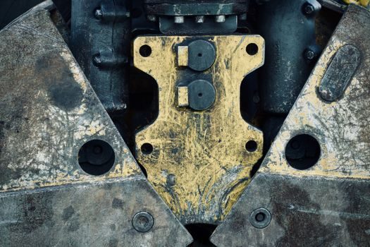
Spalled concrete around the embed during bolt torque-up: root cause is shallow embed depth or insufficient edge distance; corrective action is stop, photograph, escalate to the EOR — do not add a larger washer and continue. A larger washer masks the symptom but does not move the cone of influence that produced the spall. [S2]
Anchor rotates freely during torque: root cause is the adhesive or grout column didn't develop, often because the hole was wet at install; corrective action is remove the anchor, re-drill at 2× diameter offset, and re-install after the hole is bone-dry (compress-oil-free air and a desiccant blast on humid days).
Bolt threads stripped at the rated torque: root cause is wrong nut grade (e.g., a Grade 5 nut on a Grade 8 stud, or mismatched metric/SAE threads); corrective action is replace the complete fastener set, not the nut alone. Mixing grades silently derates the joint by 20-30%.
Acceptance Criteria and When to Replace, Not Repair
A typical embedded-part acceptance pass requires three conditions: torque within ±5% of the specified value on a calibrated wrench, no visible spalling or cracking at the embed-concrete interface under a 1.0× design load hold, and as-built position within the drawing tolerance. Any miss on any one of the three is a fail. [S3]
Replace, do not repair, when the embed has moved more than 2× the drawing tolerance, when the concrete cone has visibly spalled, or when the field pull test creeps. Repair options (epoxy injection, larger washer, additional anchor) are case-by-case and require EOR sign-off, not a foreman's call. If the equipment interface is also out of tolerance — for example, a baseplate sitting on a misaligned grout pack more than 25 mm thick — the spec usually requires a re-pour rather than a deeper grout bed, because thick grout shrinks and cracks.
Two trackable signals after install: monitor the first 72 hours of equipment operation for any new cracking radiating from the embed (a sign of undersized bond), and re-torque after the first thermal cycle if the equipment runs hot (>80°C) — heat relaxes the pre-load and a re-torque restores the clamp load to design value. Crews that skip the 72-hour walk-through routinely miss the early-warning cracking that would have shown them an undersized bond.
For shop-floor installs where the embed sits in a machined surface — a locating pin in a jig plate, a dowel in a fixture — the same prep-set-verify sequence applies but the tolerance band tightens to ISO 2768-fine and the verification is usually a dial-indicator runout check at ±0.01 mm. The linear-guide and crossed-roller-guide systems that ride on these plates are unforgiving of runout above that band.
Cross-reference for similar on-site procedure walkthroughs: Gravity Die Casting Machine Installation: Foundation, Rigging and Commissioning covers a parallel foundation-tolerance workflow for foundry equipment, and the Function Generator Buying Guide 2026: Bands, Specs, Sourcing walkthrough shows the same prep-verify pattern applied to bench-top instrumentation.