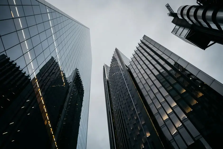
Wind-driven lateral load, not gravity alone, governs steel section choice above roughly 30 storeys, and a 2025 performance-based study on 10/20/30/40-storey models ranks core shear walls, tube systems, and X-bracing as the top configurations for cutting storey drift and overturning moment [S2].
Selection typically means choosing a lateral system (moment frame, braced frame, shear wall, outrigger, or tube) and pairing it with gravity sections (wide-flange H, hollow structural section, built-up box) sized for axial demand, with grade escalations from carbon steel to alloy steel as column loads rise [S3].
Why section choice pivots on wind and seismic drift above 30 storeys
The published wind study benchmarks five lateral systems on identical 40-storey frames: moment-resistant frame, corner and centre shear walls, V- and X-bracing, and framed-tube; core shear walls deliver the lowest lateral displacement and overturning moment across the suite, with X-bracing competitive on shorter high-rises but losing efficiency past 30 storeys [S2]. Storey drift is the binding check at 40 storeys, not member strength, which is why tube action (closely spaced perimeter columns tied by deep spandrel beams) keeps qualifying as the reference solution for slender towers [S2][S3].
Base shear scales with building height, so engineers size foundations and lower-storey columns for combined axial and bending demand; moment frames are workable up to about 20 storeys before drift becomes uneconomical, and braced frames (X or V) sit between frames and walls on the stiffness/cost curve [S2]. For practical product mapping, the relevant section family is wide-flange beams (HEA/HEB/HEM per European nomenclature or W-shapes per AISC), square and rectangular hollow sections (SHS/RHS), and circular hollow sections (CHS) for diagonal bracing.
Section family vs. role: gravity columns, perimeter tubes, and brace diagonals
Gravity columns in the 40-storey band commonly use heavy wide-flange sections (HEM 600 and above, or W14×500 class) or built-up box sections fabricated from quenched and tempered alloy steel plate when section depth is constrained by floor-to-floor height; stainless steel is reserved for exposed architectural piers and facade columns where corrosion resistance outweighs material cost. [S1]
Perimeter tube columns (the Seagram/DeWitt-Chestnut lineage) are typically W14 or box-built, spaced 1.5–3.0 m on centre and tied by deep spandrel beams; this geometry activates frame-tube action, where the whole perimeter behaves as a perforated cantilever, and is the standard answer for 40+ storey towers when drift governs [S2][S3]. Brace diagonals take circular hollow sections (CHS) for uniform torsional stiffness, with silicon steel only entering the picture for transformer cores in the building's MV switchroom, not the structure itself. For a parallel non-structural selection exercise, the same spec-first logic maps to silicon-steel grades for oil and gas service, where grade and lamination thickness are the binding criteria.
Criteria-based comparison: lateral systems on 40-storey frames
From the published 10/20/30/40-storey benchmark, four decision criteria separate the five systems at 40 storeys [S2]:
1. Storey drift: core shear wall < framed tube < X-bracing < V-bracing < moment frame. The wall-and-tube pairings sit at the top of the ranking, while a bare moment frame drifts beyond typical 1/500 limits at 40 storeys without stiffening [S2].
2. Base shear efficiency: braced frames (V and X) mobilise the highest base shear per tonne of steel, useful where foundation capacity is constrained; core walls are the most material-efficient when a service core already exists [S2].
3. Constructability and let-through floor area: X-bracing blocks facade openings and is normally hidden in service cores; moment frames preserve open layouts but at a steel tonnage penalty of roughly 20–40% over a braced alternative at 30 storeys.
4. Ductility and seismic overlap: in seismic zones, shear walls and tube systems also provide the mass and overstrength to satisfy capacity-design rules; moment frames need special detailing at beam-column joints to qualify, which adds fabrication cost. As the study concludes: "core shear wall performs outbound among all divisions of structural systems by providing adequate performance and stability in structures by reducing the drift and displacement response" [S2].
Material grade escalator for high-rise columns and braces
The default starter grade for hot-rolled wide-flange columns in commercial high-rises is a structural carbon steel such as ASTM A992 (Fy = 345 MPa) or European S355JR/J0 per EN 10025-2, which covers the bulk of beams and standard columns. Once column loads approach 20–30 MN at the base of a 40-storey tower, the section size climbs past rolled W14 limits, and the spec moves to built-up box columns fabricated from ASTM A572 Gr. 50 plate (Fy = 345 MPa) or, for thinner walls, ASTM A913 Gr. 65 (Fy = 450 MPa) quenched and tempered alloy steel. [S2]
For brace diagonals, the typical choice is a cold-formed or hot-finished S355 circular hollow section; in seismic regions, EN 10025-4 S355ML or S460ML adds improved through-thickness Z-performance to guard against lamellar tearing at gusset connections. Plate thicknesses for built-up box columns in the lower 10–15 storeys commonly run 50–100 mm, with longitudinal seam welds subjected to UT inspection. Architects occasionally substitute stainless steel EN 1.4404 (316L) for exposed perimeter columns, accepting roughly four times the unit material cost for corrosion immunity and a polished finish, with a typical yield around 220 MPa [S3].
Connections, fabrication gates, and tolerances that fail the section

Three fabrication gates disqualify a section on paper long before it reaches site: (a) flange thickness above ~100 mm in carbon steel triggers Charpy and Z-direction testing per EN 10164 to limit lamellar tearing at column splices; (b) heavy built-up boxes demand UT or RT on full-penetration butt welds with acceptance per AWS D1.1 or EN 1090-2 execution class EXC3/EXC4; (c) shop-bolted connections to braces use slip-critical bolting (e.g. ASTM A325/A490 or EN 14399 HR bolts) with faying-surface preparation to a defined slip coefficient, usually Class B. [S1]
Section length is a quiet constraint: rolled sections ship economically up to about 18 m, beyond which splice costs and transport permits dominate; the default for high-rise columns is therefore a 3-storey splice pattern, with shop-welded head-to-base plates and field-bolted splices sized to transfer both axial load and a defined bending moment for drift compatibility. For more on the spec map for adjacent applications, see steel section choice for hospital buildings, where shorter spans and tighter hygiene tolerances push section family in a different direction.
Who this section strategy is for, and where it stops fitting
The core-wall-plus-tube + heavy alloy steel box-column recipe fits commercial office towers of 30–60 storeys in CWC C (or wind class III) or higher exposure, mixed-use slabs in dense Asian and Middle Eastern cities, and residential towers over 40 storeys where drift under 1/10-year wind controls [S1][S2]. It is the wrong starting point for low-rise industrial sheds (where steel section gravity members under 200 kg/m dominate), for short-span hospital slabs covered by steel section selection for hospitals, and for buildings under 10 storeys where a moment frame in carbon steel is the default.
It is also the wrong starting point where the lateral system is concrete shear walls through the full height, in which case the steel is reduced to secondary beams and composite deck; composite construction with concrete-filled steel tubes (CFST) is a hybrid that shifts the design into AISC 360 Chapter I and EN 1994-1-1 territory, and selection criteria change accordingly. Watch the next spec move: EN 1993-1-1 and EN 1993-1-5 updates on high-strength quenched and tempered plate above S460, and the spread of AISC 360 provisions for 690 MPa steel in seismic bracing; either of these will reset the grade escalator at the base of 50+ storey towers within the next design cycle [S2][S3].