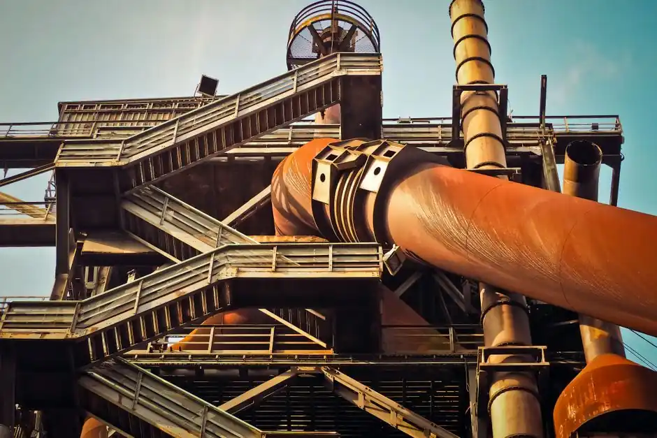
Stepped pipelines are sections of progressively larger pipe diameter installed along a conveying line to counteract the velocity rise caused by gas expansion as static pressure drops toward the receiver [S1][S2]. The technique is most often cited for dilute-phase, positive-pressure systems where the air mass flow is constant but the gas volume grows as pressure falls.
Design references frame stepped-pipe sizing as a trade-off between added fabrication cost and tighter velocity control, with the operational window for dilute-phase gas velocity widely reported as 4,000–8,000 fpm, and dense-phase flow intentionally run below the saltation velocity of the material [S2][S3].
Why Velocity Rises in a Single-Bore Pipeline
A pneumatic conveying line has higher pressure at the feed end and lower pressure at the discharge end; the resulting expansion of the conveying gas forces volumetric flow (and therefore gas velocity) to climb along the pipe [S4]. For a fixed mass flow, halving the absolute pressure roughly doubles the specific volume, so on a long, high pressure-drop run the exit velocity can be far higher than the inlet velocity [S3].
Consequences of that uncontrolled velocity rise include increased pressure drop, material breakage, accelerated pipe wear at bends, and material build-up if the local velocity later collapses back below the saltation point [S4]. Material testing published in 2023 (MDPI Applied Sciences) further confirms that conveying air speed, particle mass flow rate, pipe diameter, and particle size are the four dominant variables governing internal velocity distribution [S6].
Stepped-Pipe Sizing Logic and Practical Velocity Bands
Stepping the pipe means welding or flanging a larger-bore section downstream of a smaller-bore run, typically with one or two transitions rather than a continuous taper, so that the local velocity in each segment is held closer to the design point [S4]. The textbook rule of thumb, repeated in multiple training notes, is to consider stepping the diameter for any dilute-phase line with a total pressure drop of about 7 psi (≈0.48 bar) or higher, where gas expansion will otherwise push exit velocity well past the inlet target [S3].
For reference, common minimum transport velocities cited for dilute-phase suspension flow are 2,500–6,000 fpm, with normal operating bands of 3,200–8,000 fpm depending on material density and particle size [S3]. Dense-phase operation sits at the lower end of that window or below, and is one of the modes where stepped lines are deliberately used to keep a plug-flow pattern from re-entering dilute suspension [S7][S8].
Comparison of Pipeline Approaches for Velocity Control
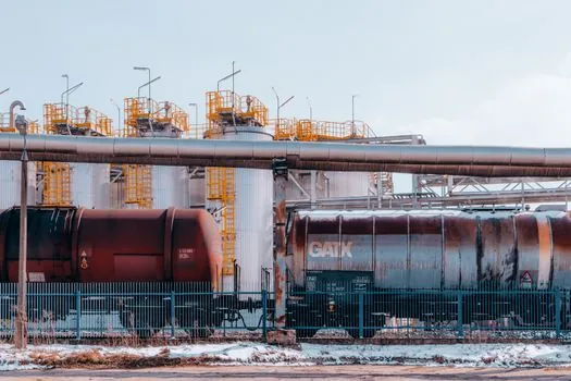
Engineers usually choose between four pipeline strategies; the decision hinges on system length, allowable pressure drop, material friability, and budget. The table below lines them up against the criteria that matter most in pipeline pump and conveying selection work. [S5]
Single-bore, constant-diameter pipe is the cheapest and simplest, and is adequate for short runs with pressure drops well under 7 psi [S3]. Stepped-pipe (one or two diameter increases) adds flanges and reducers but keeps long-run velocity near the design point, with the caveat that every step must still hold velocity above the saltation and choke limits of the product [S4]. Variable-speed blower control trims air volume rather than pipe area, and works well when the same line must move multiple products at different rates, but cannot by itself stop erosion at a fixed overspeed point [S2]. Dense-phase conversion (running intentionally below saltation) is the most velocity-friendly option for fragile or abrasive solids, but requires pressure-rated pipe, booster injectors, and confirmed material testing before commitment [S7][S9].
Design Workflow and Precautions for Stepped Lines
The standard workflow for any pneumatic conveying design starts with material properties (bulk density, d50/d90, shape, abrasiveness, moisture, friability, explosivity), then picks a conveying mode and minimum transport velocity, then selects pipeline bore, then calculates system pressure drop, then sizes bends and the air source, and only then decides whether stepping is required [S5]. Within that sequence, the pressure-drop step is where stepping is usually introduced, because the calculated exit velocity exceeding the inlet target by more than 15–20% is the common trigger [S2][S3].
Two precautions are emphasised in the engineering literature. First, the downstream velocity inside every stepped segment must remain above the material's saltation velocity and above its choke velocity, otherwise the line will plug; this constraint is especially important if a higher-velocity flushing step is part of the operating procedure [S4]. Second, an economic study should confirm that simply re-selecting a single larger bore, changing the solids loading ratio, or adjusting the blower cannot deliver the same velocity profile at lower capital cost before specifying stepped transitions [S4]. Forced-air supply hardware such as control valves on the air main and control cabinets for blower VFDs still need to be sized for the higher volumetric flow that the larger downstream bore will see at the same mass throughput.
Failure Modes and Operating Limits
Plugging is the dominant failure mode in stepped-pipe systems, almost always traceable to a transition that drops local velocity below the saltation point for the conveyed product [S2][S4]. The second most common issue is accelerated elbow wear on the smaller upstream bore, since the inlet segment still carries the highest particle velocity and solids loading ratio; hardened or ceramic-lined bends are commonly retrofitted in response [S2][S5].
For abrasive minerals, cement, and fly ash, a 4,000–6,000 fpm gas velocity with a solids-to-air loading ratio of no more than 15 is a typical dilute-phase target; running above that window with no stepped transition is the usual root cause of the wear problems seen in field service [S7]. The 2023 MDPI study also documents that increasing pipe diameter at constant airflow reduces particle-wall interaction energy, which is consistent with the wear-reduction claim attributed to stepped designs in vendor literature [S6].
Standards, Sourcing, and Selection Signals
No single ISO or ASME standard governs stepped-pipe geometry directly; pneumatic conveying design is instead driven by vendor methods, PDH training material such as CED Engineering course M05-010, and reference texts cited in industry papers [S3]. For hazardous powders (combustible dust, reactive materials) the relevant cross-standards are NFPA dust-collection rules and ATEX 2014/34/EU equipment directives, but those apply to area classification and equipment certification rather than to stepped-pipe layout itself [S3].
Selection signals to watch over the next design cycle: explicit stepped-bore geometry offered as a standard option on long-run dilute-phase packages, increasing use of CFD-driven bore optimisation (the MDPI 2023 paper is an early indicator of this trend moving into vendor tools) [S6], and more frequent pairing of stepped pipelines with VFD-controlled blowers to widen the operating window without re-piping. For an adjacent spec reference that pairs well with this material, see the steel vs concrete deck truck scale decision guide, which uses the same criteria-based comparison approach for a different equipment class.