
A strain gauge bridge outputs low dc millivolts (typically 1-3 mV/V) that require bridge excitation, amplification, and filtering, which a dedicated signal conditioner provides as a single function block.
A signal isolator performs a different job, breaking ground loops and rejecting common-mode noise with galvanic isolation rated up to several kV, with no native bridge excitation. For weighing, force, and load-cell channels, the two functions overlap on isolation but diverge on excitation and linearization [S1][S3][S4].
What Each Device Actually Does on a Strain Gauge Channel
A load cell or strain gauge produces a millivolt-level differential output proportional to applied force, sitting on a high common-mode voltage from the bridge excitation. A strain gauge signal conditioner must supply a stable excitation voltage (commonly 5 V or 10 V), amplify the millivolt signal with low noise, reject the common-mode component, and linearize the bridge output [S3][S8]. Without excitation, the bridge cannot operate, so a pure isolator cannot replace a conditioner on this input type [S10].
An isolator's job is galvanic separation between input and output, with no requirement to drive a bridge. Dataforth notes that isolated signal conditioning modules use up to four levels of isolation to break ground loops and reject induced field noise, with input-to-output isolation commonly rated at 1500 Vrms or 2500 Vrms for industrial DIN-rail units [S4]. A standalone isolator has no excitation source, so it cannot energize a 350 ohm load cell on its own [S5][S9].
Selection Criteria: Conditioning, Isolation, or Both
The decision on a strain gauge channel comes down to four specs: bridge excitation current (typically 30-120 mA to drive 120-1000 ohm bridges), input range (often +/- 10 mV to +/- 500 mV full scale), isolation voltage rating, and output type (4-20 mA, 0-10 V, or serial) [S1][S2][S5].
For a single remote load cell with long cable runs (above 3-5 m) or installed near VFDs and motor starters, spec a unit that combines both functions, such as the OMEGA DRST-BG bridge/strain gauge transmitter or the Acromag TT351 four-wire transmitter, which integrate excitation, amplification, and galvanic isolation in one DIN-rail package [S1][S2]. For a clean, short-run application such as a bench test stand with under 3 m of shielded cable, a non-isolated conditioner plus an external signal isolator is acceptable and saves cost [S4][S8].
Comparison Matrix: Conditioner vs Isolator vs Combined
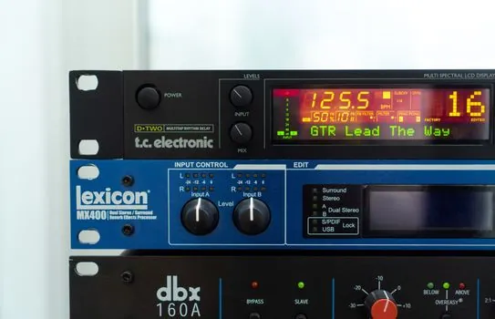
Pure strain gauge signal conditioner: provides bridge excitation (5-10 V, up to 120 mA transducer power) and mV-level amplification; isolation is optional, often missing on low-cost units. Standalone signal isolator: provides galvanic isolation (commonly 1500-2500 Vrms) and common-mode rejection, but no excitation and no bridge linearization. Combined isolated strain gauge conditioner: provides excitation plus amplification plus 1500-2500 Vrms galvanic isolation in a single unit, which is the dominant spec for new plant builds [S1][S2][S4][S9].
On cost, a bare conditioner is the cheapest, a combined unit sits in the middle, and pairing a separate conditioner with a standalone isolator is the most expensive and panel-space-hungry option. On wiring, the combined unit uses one part number, one set of screw terminals, and one calibration procedure, which reduces commissioning time on multi-cell scales [S2][S5][S8].
When Isolation Is Non-Negotiable on a Strain Gauge Channel
Three field conditions force isolation. First, ground potential differences above a few volts between the load cell and the PLC cabinet, common on outdoor silos, tank farms, and long conveyor runs. Third, multi-cell weighing platforms with paralleled load cells, where cell-to-cell ground paths create measurement drift [S4][S9].
Dataforth highlights that common-mode voltage and source impedance together drive crosstalk and ground-loop errors, and recommends keeping source impedance below 100 ohm by placing an isolation amplifier close to the sensor. For load cells with 350 ohm bridge resistance, the isolator must be at the cell end, not the cabinet end, to be effective [S4][S8]. A practical follow-up is proper cable dressing, covered in shielded cable selection for load cell and strain gauge signal runs, since even an isolated conditioner will not fix a cable routed in the same tray as a 480 V VFD output.
Standards, Ratings, and Spec Anchors
Bridge conditioner modules commonly advertise EMC immunity to RFI, EMI, ESD, and EFT per IEC 61000-4-x test methods, with isolation voltages of 1500 Vrms or 2500 Vrms between input, output, and power [S1]. Operating temperature for industrial DIN-rail units is typically -20 to 70 C, and transducer excitation current is often published as up to 120 mA to drive four 350 ohm load cells in parallel [S1][S2].
The selection guide from DigiKey, dated 2023-07-18, groups both functions under "Signal Conditioners and Isolators" and lists isolation voltage, input range, output type, supply voltage, and mounting type as the five primary selection keys, which is the same framework an engineer should use to compare strain gauge modules side by side [S5]. Acromag, OMEGA, and Dataforth product lines all show this five-key structure, and Dataforth specifically ties isolation to the elimination of ground-loop currents rather than to signal conditioning per se [S4][S5].
Who Should Use Which
Spec a dedicated signal conditioner without isolation when the load cell is within 3 m of the indicator, the cable is shielded and grounded at one end, and the cell shares a clean ground reference with the readout, typical of lab balances and machine tool force sensors. Spec a combined isolated conditioner when the cell is remote, the plant has VFDs, or the application is a process scale that will see regulatory inspection [S1][S2][S4].
Spec a standalone isolator only when an existing non-isolated conditioner is already installed and the field problem is a documented ground loop, because adding a second device doubles the calibration chain and the panel footprint. For new builds, the combined unit is the default. For weighing applications with more than one load cell, the DRST-BG and similar bridge transmitters also support remote sense wires to compensate for cable resistance, a feature that bare isolators do not provide [S2][S8].
Watch for two trackable signals over the next 6-12 months: the rollout of Ethernet-APL enabled bridge transmitters that combine 4-20 mA signaling with two-wire power and digital diagnostics, and the migration of bridge conditioner ICs (1B32-class parts) to higher integration levels that put excitation, amplifier, and ADC on a single die for OEM load cell designs [S6].