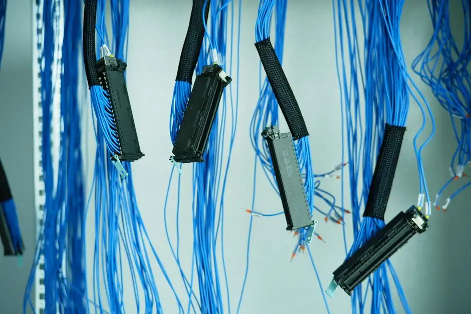
A 360-degree bonded braided copper shield, terminated at both drive and motor ends to a common ground, is the engineering baseline for containing common-mode current and PWM switching noise on a VFD-to-motor run [S1][S5].
The same AP040076EN app note sizes the analog signal pair at 20 AWG shielded, the relay conductors at 14 AWG, and general control at 16 AWG, with all control wiring rated for 600 V [S1]. Routing the motor cable at least 3-4 inches from the control/speed cable is the practical spacing rule for short and medium runs, with shielding on the control side recommended over 6-8 ft [S2].
Why VFD output cable is a power cable, not a control cable
PWM switching in modern drives produces voltage spikes and reflected waves that reach two to three times the source DC bus voltage at the motor terminals, which is well outside the stress envelope of standard THHN or 14/4 building wire [S3]. A purpose-built VFD cable carries three power conductors, a grounding conductor, an overall metallic braid, and a chemical- and oil-resistant jacket; ratings typically land at 600 V or 1000 V with conductor sizes from 10 AWG to 500 kcmil, dry ratings to 90 degrees Celsius, and cold-versions rated to -40 degrees Celsius wet [S4]. The braid is the key functional element: it gives noise a low-impedance path back to the drive bus instead of letting common-mode current find its way through motor bearings and stray equipment grounds [S1][S3].
Specifying commodity shielded cable as a substitute, where a 100 percent coverage braid is replaced with a foil or spiral wrap, is a known source of bearing EDM and ground-loop heating in VFD-driven motor systems [S3][S5].
Control-side shielded cable: 20 AWG analog, 16 AWG digital, 600 V jacket
For the low-energy harness between the VFD and the speed pot, PLC analog input, encoder feedback, or tachometer, Eaton's AP040076EN prescribes a 20 AWG shielded cable for analog signals, 14 AWG for relays, and 16 AWG for other control, with the whole assembly rated to 600 V [S1]. Unlike control wiring, a VFD cable's shield is intended to carry common-mode current noise in addition to noise from magnetically-induced coupling [S6].
Field installs on hobby and light-industrial machines frequently skip shielded control cable for runs under 3-5 ft because radiated coupling to a home stereo is not a fault condition, but the same thread documents that shielded motor cable becomes the safer call once the run exceeds 6-8 ft [S2]. For racks carrying analog 4-20 mA or 0-10 V speed references adjacent to a VFD output, the shielded control cable approach is treated as standard, not optional [S1][S6].
Termination: 360-degree bond, both ends, common ground
Proper shield termination is a 360-degree bond between the cable shield and the grounding system at both the drive end and the motor end, with the drive and motor tied to a common equipment ground [S5]. Pigtail terminations are the most common field failure mode: the pigtail acts as a high-impedance antenna at the PWM fundamental and its harmonics, so the noise the shield was supposed to drain is re-radiated into the cabinet [S5][S6].
Eaton's AP040076EN is explicit that for input and output motor leads the shield should be terminated on both ends to keep a common ground throughout the system, and that a metal conduit can substitute for a shield only if the contact points do not inject additional noise [S1]. The TPC/ATPC guidance reinforces the 360-degree approach on the VFD cable side, with braided copper construction preferred over tape for longevity and low impedance [S3].
Routing and segregation: distance, crossings, parallel runs
Eaton recommends at least one inch of separation between parallel runs of input and output VFD power cables, with any required crossings made at 90 degrees to limit inductive coupling [S1]. On the control side, keeping the motor cable at least 3-4 inches from the control/speed cable is the practical rule in hobby and small-panel installs, with 90-degree crossings as the secondary mitigation [S2]. The VFD cable itself, by virtue of its braid and jacket, is what allows closer routing than would be acceptable with unshielded motor leads [S3][S4].
For a wider system view, the relationship between a VFD and the surrounding wiring duct layout is just as important as the cable spec: signal-carrying duct should not share a run with VFD output duct, and any required crossover should land in the shortest possible perpendicular segment [S1][S5].
Comparison: VFD power cable, shielded control cable, and unshielded general-purpose
The three cable types most often confused on a VFD panel are VFD-rated power cable, generic shielded control cable, and commodity 14/4 or THHN. The key decision criteria: voltage spike withstand, braid coverage, shield termination method, and qualification for cable-tray runs. [S4]
VFD-rated power cable is built for 2-3x source-voltage transients, uses a high-coverage copper braid plus a full equipment ground, and is qualified to 600 V or 1000 V with 90 degrees Celsius dry ratings [S3][S4]. Generic shielded control cable (for example, 20 AWG shielded twisted pair at 600 V) is right for the analog reference and tachometer return between the drive and the controls, but is not rated for the drive-to-motor link because its insulation thickness and braid cross-section are sized for low-current signal duty [S1][S6]. Unshielded 14/4 is fine on the input line side upstream of the drive and acceptable on the output side only for very short runs (under roughly 3-5 ft) where the radiated energy from a few feet of unshielded lead is too small to matter [S2][S5].
One grounding caveat matters for all three: HART and other 4-20 mA signaling rides a 4-20 mA analog loop, while Foundation Fieldbus and PROFIBUS PA are fully digital protocols, so a shield termination scheme that works for HART will not necessarily match a digital fieldbus segment [S1]. When in doubt, terminate the shield at one end only on the fieldbus segment, or follow the fieldbus-specific guidance from the device supplier.
Reliability data and failure modes tied to the wrong cable spec
Field data compiled from 2025-2026 service reports attributes more than 80 percent of early VFD failures to preventable installation and commissioning decisions, with overheating at 50-60 percent and overcurrent/overload around 30 percent; bearing damage from electrically induced discharge machining is reported on roughly 50 percent of VFD-driven motor systems when no mitigation is in place [S5]. The cable spec directly drives two of those categories: insulation breakdown from unmitigated voltage spikes and bearing EDM from common-mode current seeking a path through the motor frame.
For installers weighing whether to spend on a VFD-rated cable or a general-purpose shielded cable, the cleanest trade is at the drive-to-motor run: VFD-rated cable there, and a smaller-gauge shielded cable on the analog harness back to the control, with the motor cable kept physically segregated from the control bundle by 3-4 inches minimum and routed at 90 degrees on any crossing [S1][S2][S3]. Practitioners who have tried unshielded wiring for years on hobby machines often report no issues, but those same machines are short, low-power, and away from sensitive analog equipment [S2].
A related design thread that runs alongside the VFD question is high-flex shielded robot cable selection, which covers the same braid-plus-jacket logic for continuous-flex applications where standard VFD cable would fatigue in weeks.
Trackable signals for the next planning cycle: NEC 2026 adoption state-by-state for any revised VFD cable article language, and OEM releases of low-voltage 24 V VFDs aimed at the hobby-machinist segment, where cable shielding decisions are still being made run-by-run rather than by spec.