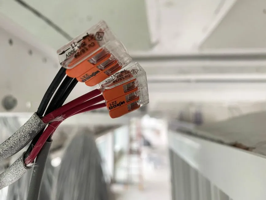
For load cell and strain gauge signals in the millivolt range (typically 0 to 30 mV output on a 5 to 10 V excitation) the cable is part of the measurement chain, not a passive hookup wire [S3]. Resistance drift in the conductors, and any EMI/RFI that couples into the mV signal, show up directly as zero drift, span error, and noisy weight readings.
The two practical decisions are: 4-wire vs 6-wire construction, and how the shield is terminated. Get either one wrong and you either lose calibration when the cable is shortened, or you build a ground loop that injects 50/60 Hz into the bridge reading [S1][S6].
4-wire vs 6-wire: which one fits the run
4-wire load cell cable carries excitation+ / excitation- / signal+ / signal- and is calibrated to its shipped length; cutting or significantly extending it shifts conductor resistance and voids the factory cal on most commercial scales [S3]. It is the right call only for short jumpers between a scale base or junction box and the indicator, where the bundled cable length matches what the cell was calibrated against [S3].
6-wire cable adds a dedicated sense+ / sense- pair that lets the indicator read the actual voltage at the bridge and trim excitation to compensate for lead resistance. That is why 6-wire is mandatory on long runs, on sites with wide ambient temperature swing, and anywhere the cable may be cut to length in the field [S1][S3]. If a 6-wire cell must land on a 4-wire indicator, the excitation and sense terminals must be jumpered correctly; otherwise the indicator throws an "Open Sense" fault or stays unresponsive [S1].
Shield construction: what to actually order
Standard load cell cable uses an aluminium/polyester foil tape shield combined with a tinned-copper braided shield, under an outer PVC jacket. The braid gives mechanical robustness and low DC resistance for shield termination; the foil closes the gaps at high frequency [S3]. For multi-pair variants, the HBM Type 139B cable adds an individual shield on each pair in addition to the overall shield, with an outer diameter around 7.5 mm [S5]. Artech's general-purpose offering uses 22 AWG conductors with several jacket and shielding options to match environment [S8].
Twisted pair is not optional. Both mechanisms are needed because load cell output sits in the tens of millivolts and is easily swamped by line-frequency interference [S1][S4].
Shield termination rules that prevent ground loops

The shield is not part of the measurement bridge and must never be used as a current-carrying ground for the indicator [S1]. The correct pattern is a single-point ground at the indicator (or amplifier) end only, with the cell end of the shield left floating or tied to the cell body through its own mounting bond, not through the cable shield conductor [S1][S6].
When a connector sits in the run, the drain wire goes to the connector shell or to the ground pin on the indicator side of the connector, not on the sensor side: this keeps the shield path continuous through the mated pair without creating a second ground point at the load cell [S7]. For weigh systems that must survive industrial EMI (VFDs, motor starters, welding inverters), the same rule applies to any in-line junction box: shield continuity through the box, ground lifted at the cell, bonded at the indicator [S6].
Selection criteria, side by side
Use the four criteria below to size a cable before quoting it on a drawing: [S4]
1. Run length. Under roughly 10 to 15 m with stable ambient temperature, a 4-wire cable that ships with the cell is acceptable and keeps cost down [S3]. Beyond that, or anywhere temperature varies by more than 10 to 15 K across the run, step to 6-wire with sense leads so the indicator can correct for lead resistance [S1][S3].
2. Environment. Indoor, light industrial: PVC jacket with foil + braid is fine [S3]. Washdown, food, chemical exposure: specify a polyurethane or TPE jacket, and keep the braid coverage high (typically 85% or above, supplier-dependent) for mechanical life. Where individual pairs need isolation, follow the multi-shield construction pattern used in HBM Type 139B [S5].
3. EMI floor. Near VFDs, welding, or large contactors: pair the overall shield with individually shielded pairs, keep the run in its own shielded cable conduit, and maintain single-point grounding. The signal level (0 to 30 mV) [S3] has no headroom against a poorly terminated shield, and any improvement here is cheaper than adding filtering at the indicator.
4. Field serviceability. If the cable will be cut to length during install or replaced periodically, 6-wire is the only honest answer, because shortening a 4-wire load cell cable generally forces a full re-calibration and can void the scale warranty [S3]. A load cell module with on-board amplification can relax the mV-budget concern but does not change the shielding rules.
Where shielded cable does not fix the problem

Shielding cannot compensate for a cell mounted without a proper mechanical ground path, for a cell that is itself misaligned and seeing side load, or for an indicator with a poor analog front end. The shield also cannot fix a system that has the shield grounded at both ends; that configuration builds a ground loop whose 50/60 Hz current flows through the shield and magnetically couples into the mV pair underneath [S1].
It is also a mistake to substitute a generic 4-conductor shielded signal cable for a load cell cable just because the conductor count matches. Load cell cable is specified for a defined conductor resistance per length, a defined characteristic of the shield, and (in the 6-wire case) a defined pairing of sense leads. Generic cable may pass continuity but fail noise or drift tests in service [S4]. For new builds it is worth confirming the cable part number against the cell's calibration certificate, and against the strain gauge and load cell datasheets the cell ships with.
Standards and sourcing signals worth tracking
There is no single ISO or IEC standard that dictates load cell cable construction; instead, the wiring rules are enforced indirectly through the cell's performance spec (non-linearity, creep, temperature coefficient of zero and span) and through the indicator's input common-mode rejection. What is standardised in the broader signal-wiring world is the practice of single-point shield grounding to break low-frequency ground loops, which the load cell vendors echo in their own guidance [S1][S6].
Trackable signals to watch: vendor datasheets that publish per-length conductor resistance and recommended maximum run by gauge, since these let a buyer spec 4-wire only on runs the cell was actually calibrated for; and 6-wire amplifier modules that publish sense-lead excitation tolerance, which sets the practical upper limit on 6-wire run length. A useful cross-reference for the broader sensor and wiring context is the electronic load and wiring duct entries, which cover the panel-side infrastructure this cable lands in. The timing belt selection for automotive production lines and roller chain selection for automotive production lines pieces are unrelated to cable construction but share the same factory-engineering readership and the same decision-matrix style.