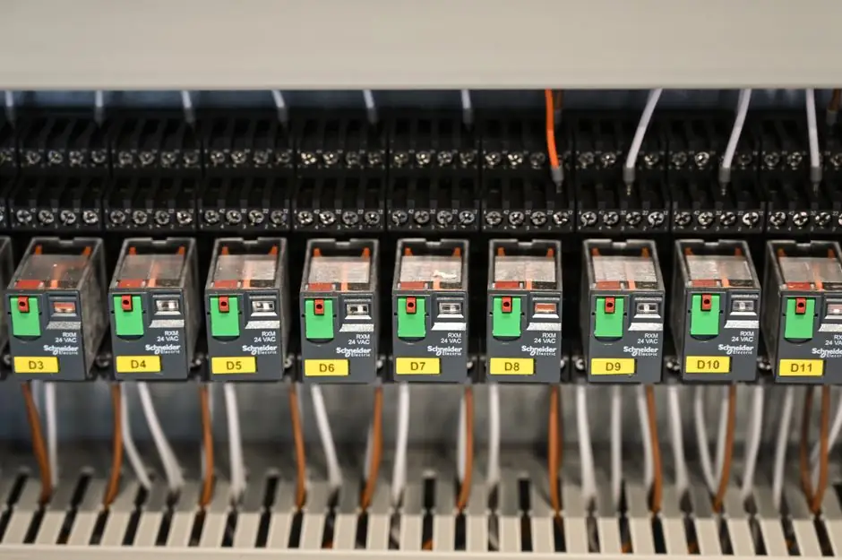
Type 1, Type 2, and Type 3 surge protective devices perform different test duties at different installation stages, with Type 1 using a 10/350 μs lightning-current impulse, Type 2 using 8/20 μs discharge currents, and Type 3 using a 1.2/50 μs and 8/20 μs combination wave.
For low-voltage AC installations, Type 1 devices address lightning-current duty at the supply origin, Type 2 devices protect downstream distribution boards, and Type 3 devices provide supplementary protection close to sensitive equipment [S2][S5].
SPD classifications by installation and test duty
Type 1 SPDs are permanently hard-wired devices intended for installation between the secondary side of the utility service transformer and the line side of the main service equipment’s overcurrent protective device; permitted arrangements may also place them on the load side of the main service equipment [S1].
Type 2 SPDs are installed on the load side of the main service equipment’s overcurrent protective device, including at the service entrance only when the specified upstream connection rules are met [S1]. In IEC practice, Type 1 is associated with Class I lightning-current duty, Type 2 with Class II distribution-level surge duty, and Type 3 with Class III supplementary protection [S5].
North American UL 1449 classifications emphasize placement relative to the service overcurrent device, while IEC 61643 classifications emphasize test duty. Their Type 1, Type 2, and Type 3 labels are therefore not automatic one-to-one equivalents [S2][S5].
Key ratings that distinguish each SPD
For Type 1 devices, IEC 61643 uses impulse current Iimp as the defining quantity, tested with a 10/350 μs waveform through increasing impulse magnitudes up to the declared maximum [S2]. The classification establishes the applicable test duty, but it does not establish one universal Iimp value for every Type 1 product [S5].
Type 2 performance is characterized by nominal discharge current, which is associated with combination-wave testing in IEC practice, while Iimp is used primarily in Type 1 SPDs.
Type 3 devices are recognized by open-circuit voltage Uoc, tested with a 1.2/50 μs voltage and 8/20 μs current combination wave. Their limiting voltage is commonly expressed as Up, the voltage appearing across the SPD terminals under specified test conditions; a lower Up gives a lower residual stress at the protected load [S2][S5].
In UL 1449 terminology, voltage protection rating VPR is the measured limiting voltage during surge testing. A Type 2 device may also require external overcurrent protection, and a Type 1 device may be installed downstream under the applicable installation rules [S2].
Type 1, Type 2, and Type 3 compared
Type 1 is appropriate when lightning-current discharge is part of the design duty, Type 2 is the normal distribution-board choice when lightning-current duty is not required at that location, and Type 3 supplements the upstream architecture at the protected load [S5]. Type 1+2 and Type 2+3 combined markings address multiple duties in one enclosure.
Across installation position, principal test waveform, declared current or voltage quantity, and downstream role, Type 1 covers the origin or lightning-protection boundary, Type 2 covers main or sub-distribution, and Type 3 covers point-of-use protection.
A Type 1 device does not by itself guarantee complete downstream equipment protection, a Type 2 device does not perform Type 1 lightning-current duty unless tested and marked for it, and a Type 3 device does not replace upstream protection [S5]. Final selection still depends on the product ratings, system conditions, installation rules, and coordination evidence [S5].
Combined and component SPD arrangements
Type 4 SPDs are component devices integrated into other equipment rather than installed as stand-alone protective devices. Type 1, Type 2, and Type 3 component assemblies combine Type 4 components with internal or external overcurrent protection, allowing the required protection function to be incorporated into assembled equipment [S2].
The surge protector should therefore be selected as a complete protection arrangement, not only as an enclosure label. A combined Type 1+2 unit can cover the two declared duties at one location, while Type 2+3 equipment adds point-of-use protection and must still coordinate with the upstream system [S5].
Lead length is a design variable rather than a cosmetic installation detail. Factory-integrated panelboard protection eliminates external installation leads and can produce lower let-through values than a separately mounted suppressor; an integrated approach can also remove approximately 2 to 3 ft of panelboard wall space [S4].
Where each type belongs in the installation
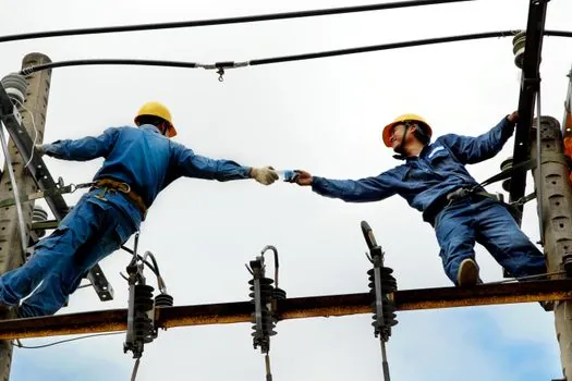
Use Type 1 where an external lightning-protection system or overhead supply may inject a substantial lightning current into the low-voltage system. Place Type 2 downstream of the service equipment where residual and distribution-level transient overvoltages require limitation, and place Type 3 close to the protected load where low-energy switching transients still need finer control [S1][S5].
Type 2 is suited to both externally induced residual surges and internally generated events such as the switching of inductive loads. Motors, transformers, air conditioners, refrigerators, pumps, compressors and other cyclic loads can generate internal surges, while lightning on nearby overhead power or telephone lines can propagate transients into the installation [S3][S4].
Type 3 is appropriate for sensitive equipment at the end of a distribution chain, but its effectiveness depends on proximity and coordination. It is not an automatic substitute for an origin or distribution-board device, and the installation should preserve the separation required by the selected product instructions and system design [S2][S5].
Surges, installation constraints, and failure limits
A surge is a short-duration voltage variation above 110% of nominal that typically lasts only 1 to 10 μs; it differs from longer events such as temporary overvoltages and swells [S4]. The classification identifies surge-handling duties, but it does not guarantee protection for every downstream load without matching voltage, current, fault-current, wiring, and installation conditions [S2][S5].
Type 3 placement has a defined UL 1449 installation condition of at least 10 m from the distribution panel, while IEC treatment places it close to the protected load [S2]. Type 1 and Type 2 position rules also differ around the service overcurrent protective device, so a supplier catalogue description cannot replace the project installation review [S1][S2].
External and internal surges must be handled as separate but coordinated problems. Type 1 addresses high-energy surges entering from external sources, while Type 2 handles residual or internally generated surges downstream; Type 3 adds point-of-use limitation for sensitive equipment [S1]. Equipment exposed to 1 to 10 μs disturbances can suffer component damage, data-processing errors, data loss and electromagnetic interference [S4].
Standards and documentation for procurement
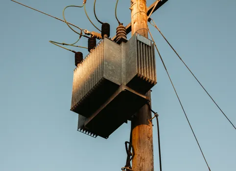
UL 1449 is used primarily in the United States, while IEC 61643 is the international framework cited for the classifications and test quantities discussed here [S2]. The procurement specification should state the required type, declared test duty, installation position, overcurrent arrangement, conductor configuration, voltage rating and applicable product listing or certification.
For IEC-based systems, record Iimp for Type 1, In and Imax where declared for Type 2, Uoc and Up for Type 3, and the applicable Up and Uc values for the protected equipment. For North American projects, record VPR and confirm whether the device is permitted before or after the service overcurrent protective device [S2].
BS 7671:2018 requires transient-overvoltage protection unless a risk assessment establishes that it is unnecessary in premises where consequences could include serious injury or loss of life, interruption of public services, damage to cultural heritage, interruption of commercial or industrial activity, or effects on a large number of co-located individuals [S3]. The standard is non-retroactive, but modified circuits should meet the applicable current requirements, and the IET guidance points to whole-installation SPD coverage where appropriate [S3].
Traceable procurement records should include the SPD type, test standard, waveform, declared current and voltage ratings, installation location, lead details, protective disconnect arrangement, and coordination with upstream and downstream stages. Those fields expose an unsuitable substitution before installation, while a maintained installation plan supports thermal aging, end-of-life indication and replacement decisions.