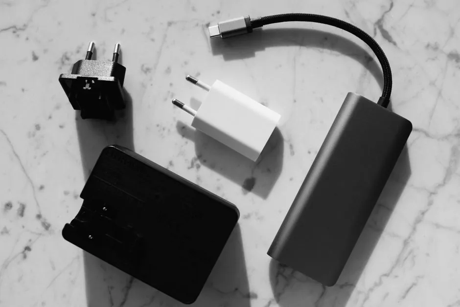
DC-DC converters divide into linear and switching categories, with buck, boost, and buck-boost topologies handling lower, higher, or bidirectional voltage-transfer requirements [S1][S2].
Classification depends on the conversion method, voltage relationship, isolation boundary, power level, regulation target, and thermal constraints, rather than output voltage alone [S2][S3].
Core DC-DC Converter Classification
A DC-DC converter changes one DC voltage level into another DC level and may also regulate output voltage or current [S2][S4]. The broad family separates into two methods: linear converters and switching converters [S2].
Linear converters pass the input through a regulating element and dissipate the voltage difference as heat, while switching converters transfer energy through semiconductor switching, inductors, capacitors, and diodes [S2][S3]. A conventional switching circuit commonly includes a MOSFET, inductor, capacitor, and freewheeling diode [S3].
Electrical isolation adds another classification layer. An isolated converter separates input and output through a magnetic or other isolation barrier, while a non-isolated converter shares a conductive input-output path. For broader context, the DC-DC converter reference covers the distinction between these conversion approaches and their practical roles.
Buck, Boost, and Buck-Boost Topologies
The three principal non-isolated switching classes are buck, boost, and buck-boost: buck lowers voltage, boost raises it, and buck-boost supports outputs above, below, or near the input level [S1][S2].
A buck converter stores energy in an inductor while its switch is closed, then releases that energy toward the load at a lower voltage when the switch opens [S1].
A boost converter stores energy in an inductor while the switch is closed and transfers it through a diode when the switch opens, allowing a lower source to feed a higher-voltage load [S1]. One specified use is raising a 3.7 V lithium-ion battery to 5 V, while renewable-energy and communications systems are additional application classes [S1].
A buck-boost converter provides a regulated output that can be above, below, or near the input voltage. The key selection test is simple: output below input points to buck, output above input points to boost, and an output that may cross the input requires buck-boost behavior [S1][S2].
Linear versus Switching Selection
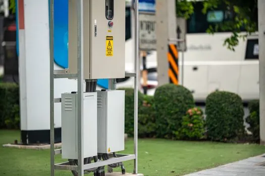
Linear regulation offers a direct path with no switching conversion, making it appropriate where low noise, simplicity, and small voltage differences matter more than conversion efficiency [S2]. Its central limitation is heat dissipation: the excess voltage is dropped across the regulating element rather than recovered as usable output power [S2][S4].
Switching converters are the stronger choice when voltage conversion is substantial, output current is high, or battery life and thermal performance matter [S1][S2]. The trade-off is switching noise and the need for careful filtering, magnetics, layout, and control design [S2][S3].
Industrial, Vehicle, and Distributed Loads
Electric vehicles use DC-DC conversion to reduce a high-voltage propulsion battery to 12 V for lighting, climate-control fans, and entertainment equipment, and the same stage can recharge the 12 V auxiliary battery [S4]. A specified industrial example is a 48 V battery feeding a 12 V subsystem through a buck converter [S1].
Distributed power systems commonly place a DC-DC converter close to the load so that upstream equipment can supply a shared intermediate voltage. Historical brick-format examples handled medium power of 400–700 W and measured 2.4 inches wide by 4.6 inches long by 0.5 inches high [S5].
Integrated power modules can also accept 85–265 VAC, correct power factor, and provide DC outputs within the same 2.4 × 4.6 × 0.5 inch package, a configuration credited with 50% board-space savings against separate arrangements [S5]. These are established distributed-power architecture examples from 2007, not present-day performance limits (2007-08) [S5].
Isolation, Regulation, and Special-Purpose Classes
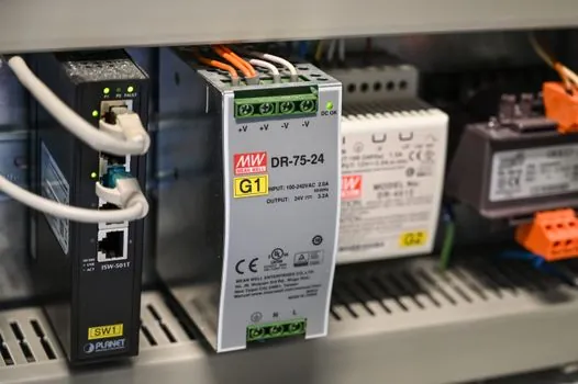
Most DC-DC converter circuits regulate output voltage, but some regulate current instead, including high-efficiency LED power sources, while simple charge pumps can double or triple a voltage [S4]. This makes output target a required specification field rather than an optional feature.
Power optimizers are a special class for maximizing harvested energy in photovoltaic and wind-turbine systems [S4]. They should not be confused with ordinary point-of-load converters. The broad technical reference for DC-DC converter classifications also distinguishes conversion function from the load being supplied.
Other classifications include non-isolated and isolated converters, regulated and unregulated outputs, and continuous-conduction versus discontinuous-conduction operation. These labels describe different properties, so they should not be presented as interchangeable categories. The decisive sequence is: first choose linear or switching operation, then identify voltage direction, isolation, regulation target, power rating, and environmental constraints.
Specification Criteria for Procurement and Design
A converter selection should start with minimum, nominal, and maximum input voltage, followed by required output voltage, tolerance, current, ripple, and whether voltage or current must be regulated [S2][S4]. The 3.7 V-to-5 V boost example and 48 V-to-12 V buck example show why one nominal input voltage is insufficient for design calculations [S1].
Thermal design must include the power dissipated or moved by the conversion stage, permitted ambient temperature, enclosure arrangement, and cooling method. Published brick examples used heat sinks or cold plates, including mounting the brick base against a metal enclosure, and eliminated a fan requirement in that configuration [S5].
Component count provides a useful architecture check: a typical switching DC-DC circuit uses a semiconductor switch, MOSFET in many designs, an inductor, a capacitor, and a freewheeling diode [S3]. Linear designs instead center on resistive or pass-device regulation, while buck and boost stages differ in switch and diode behavior [S1][S2].
Decision Rules for Converter Selection
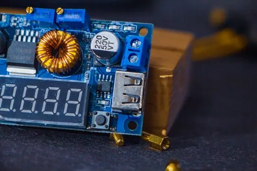
Use a buck converter when the output must remain below the input, a boost converter when it must remain above the input, and a buck-boost converter when the output can cross the input [S1][S2]. Choose linear regulation for small drops and low-noise needs, then reject it if the wasted voltage would create unacceptable heat or efficiency loss [S2][S4].
Specify isolation when the input and output domains must remain separated, and specify regulated output for equipment that requires a stable rail. Confirm efficiency, output ripple, thermal limits, component tolerances, and package size against the load rather than selecting by converter name alone [S1][S2][S5].
For procurement records, the useful next nodes are a 10% input-voltage tolerance study, a full-load thermal calculation, and a transient-response test using the intended source impedance. If those three checks are not documented, topology selection is not complete.