
A switch-disconnector combines a visible isolation gap with a defined switching duty, but it is not interchangeable with a circuit breaker.
Common classifications include off-load disconnectors, fused switch-disconnectors, non-fused devices, and high-voltage center-break, double-break, vertical-break, pantograph, and coaxial designs.
Isolation, switching and protection are separate functions
A disconnector is operated after the load current has been removed by a circuit breaker, fuse, load switch, or another rated interrupting device. Its purpose is to establish the physical isolation boundary around a line, transformer, bus section, reactor, capacitor bank, or other equipment [S2]. A visible open point supports the approved switching procedure, but it does not prove that the device can interrupt load current [S4].
A switch-disconnector is assigned both functions: it creates an isolation gap and can make or break specified nominal current. That distinction must come from manufacturer ratings, including load current, power factor, number of operations, and application category [S4]. A switch-disconnector should therefore never be described as fault-interrupting equipment unless the documentation expressly assigns that duty.
Circuit breakers interrupt load and fault current within their ratings. Load switches interrupt specified normal-load current, while earthing switches connect an isolated section to earth. These devices are often adjacent in a one-line diagram, but their functions are not equivalent [S2].
Low-voltage classifications by construction and function
DIN-rail modular switch-disconnectors are compact devices intended for electrical cabinets and distribution boards. Panel-mounted versions are used in industrial, commercial, and residential systems, while enclosed units are used for outdoor emergency disconnection and harsh environments [S1]. Enclosed products may use plastic or metal housings, with IP65 or IP66 examples listed for outdoor service [S1].
Fuse-disconnect switches combine manual isolation with fuse protection. Their internal fuses permit a circuit section to be disconnected and later re-energized, while the fuse remains responsible for overcurrent protection. Non-fused low-voltage disconnectors provide isolation and any assigned switching duty, but require separate overcurrent and short-circuit protection [S4].
The circuit breaker remains the automatic protection element for overload and short-circuit conditions. A disconnect switch, whether fused or non-fused, provides isolation for inspection, maintenance, equipment replacement, and system reconfiguration. Its continuous-current rating must not be mistaken for a fault-breaking rating [S4].
Voltage, current and pole configuration set the baseline
Select the rated voltage (Ue) to match the network voltage [S1]. Common examples are 230 V AC for single-phase systems, 400 V AC for three-phase industrial systems, and 600–1,500 V DC for photovoltaic strings, depending on configuration [S1]. Rated current In must cover the total circuit current without overheating or damage, while pole counts commonly range from 1P to 4P for the required network [S1].
Select DC disconnectors for DC systems; they may use arc-quenching chambers [S1]. Photovoltaic and energy-storage disconnectors are therefore specified for DC systems and may incorporate arc-quenching chambers for higher voltages [S1]. A 1,500 V DC device should not be selected merely because its voltage marking exceeds a 400 V AC requirement; the system type, polarity, and utilization category still govern the selection.
Switch-disconnectors are available in pole counts from 1P to 4P, depending on the network type [S1]. Pole count should reflect the electrical arrangement rather than a general preference, especially in 3-phase motor feeders and multi-pole photovoltaic strings.
High-voltage types are classified by contact movement
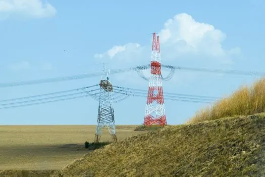
Center-break disconnectors use two rotating arms that separate at the center. They are established in outdoor air-insulated substations and require space for the horizontal blade movement and phase-to-phase clearances [S2].
Vertical-break disconnectors rotate the blade vertically, pantograph disconnectors use a pantograph geometry, and coaxial disconnectors arrange the conductive sections around a common axis. Horizontal knee or horizontal-break designs provide another geometry option [S5]. Selection depends on substation layout, voltage class, available clearances, conductor arrangement, mechanical requirements, and operating method rather than on geometry alone [S2].
These devices may be operated manually or by motor and can be paired with an earthing switch to ground the isolated section.
Performance and enclosure criteria complete the specification
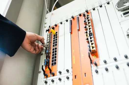
Evaluate the breaking capacity (Icu) for applications at risk of short-circuit and the operating environment, with IP65 as the minimum for outdoor use [S1]. Outdoor examples are identified with IP65 or IP66 enclosure ratings in the low-voltage classification [S1].
The project specification should separately state system voltage, continuous current, making and breaking category, pole count, operating method, enclosure rating, and installation conditions [S4]. It should also identify whether a load switch, fuse, or circuit breaker provides current interruption and fault protection. A visible gap alone does not establish load-break capability, and a continuous-current rating does not establish interrupting capacity [S4].
For maintenance work, an open disconnector does not replace lockout, tagging, absence-of-voltage verification, grounding, and access control. Outdoor blade position provides direct visual confirmation where geometry allows it; enclosed equipment may instead use a positively driven position indicator or lockable handle [S4].
Application fit separates practical device choices
Off-load disconnectors suit maintenance isolation of a line, transformer, breaker, bus section, or equipment bay after another device has removed current [S2][S4]. Switch-disconnectors and load-break designs suit feeders, ring-main units, and distribution equipment where the manufacturer assigns normal-load making and breaking [S2][S4].
Fused switch-disconnectors fit sectionalized circuits where fuses provide overcurrent protection and manual isolation remains required [S3]. DIN-rail and panel-mounted products fit low-voltage cabinets, switchboards, motor feeders, and distribution boards, while enclosed AC or DC versions serve outdoor emergency or environmental isolation duties [S1].
Integrated disconnecting switches place the disconnector within the breaking chamber, removing the need for separate disconnectors but reducing direct visibility of the open gap. Earthing arrangements and maintenance procedures must address that limitation when this construction is selected [S5].
Choosing among the principal classifications

Off-load disconnectors provide isolation but carry little or no load-interrupting duty. Switch-disconnectors add rated nominal-current switching, while fused switch-disconnectors also incorporate fuse protection. High-voltage geometry options differ mainly in contact movement, clearance needs, mechanical complexity, and installation arrangement [S2][S5].
The practical comparison is straightforward: use an off-load disconnector when a separate device interrupts current; use a switch-disconnector when one device must both isolate and switch specified load; use a fused switch-disconnector when fuse protection and isolation are combined; and select the high-voltage contact geometry after fixing voltage class, current, site clearances, and operating method [S2][S3][S4].
Before ordering, verify the product documentation against five selection criteria: rated voltage (Ue), rated current (In), pole count, breaking capacity (Icu), and operating environment [S1]. For high-voltage systems, consider the manual or motor operating method and whether the disconnector should be paired with an earthing switch [S5].
A traceable procurement record should also retain the exact switch-disconnector datasheet, rated-duty table, and project isolation sequence, because labels such as “isolator,” “load-break,” and “fused isolator” can conceal different capabilities within the product family [S3][S4].