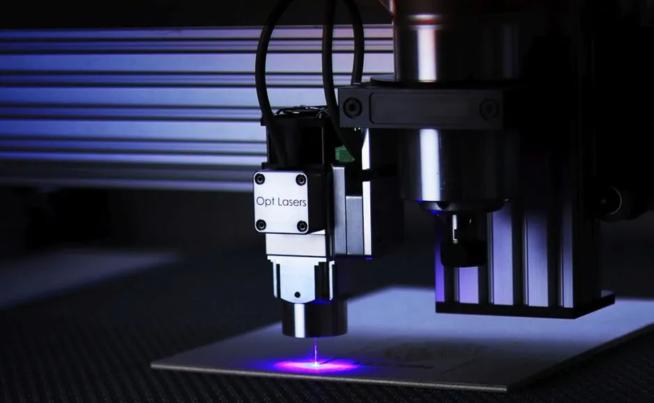
A laser sensor head can be exchanged without recalibrating the controller only if the replacement preserves the required signal, wiring, mounting, and operating behavior. A full calibration procedure is still necessary when any of those conditions changes [S1][S2].
This applies to machine-limit sensing and laser-head position feedback in laser cutters, engravers, and CNC systems, where a failed input can allow travel into the machine bed or frame [S2][S4].
Compatibility Conditions for a No-Recalibration Swap
A no-recalibration swap requires the replacement head to reproduce the original electrical interface, physical geometry, and sensing envelope. The controller cannot compensate automatically for a changed signal type, terminal assignment, or mounting offset [S1][S2].
The decision boundary is straightforward: identical or demonstrably equivalent heads may be installed as a like-for-like replacement, but any changed characteristic requires a controlled commissioning sequence. Power off and disconnect the defective sensor wires from the controller before changing terminals, and verify that the new sensor receives power after reconnection [S2].
Three checks carry the most weight. First, compare the controller input type and terminal wiring. Second, confirm that the replacement occupies the same mounting position and does not shift the target-to-sensor distance. Third, verify that the machine stops before the commanded limit is physically reached [S1][S2].
The mounting detail is not cosmetic. A sensor head must use its dedicated bracket, or the specified insulation sheet must be placed between the head and the mounting surface when the dedicated bracket is omitted [S3]. This maintains the intended mechanical and electrical arrangement, which supports the no-recalibration case only when the original arrangement is preserved.
Signal, Mounting, and Processing Criteria
Electrical equivalence is the primary criterion because the controller must recognize the replacement exactly as it recognized the removed head. A replacement that changes the input type, wiring arrangement, or diagnostic behavior is not a like-for-like substitution and requires controller-side verification [S1][S2].
Sensor technology must also match the physical target. An inductive end sensor detects metallic machine parts through electromagnetic interaction and provides non-contact detection, whereas a non-contact laser or optical sensor responds to its specified optical target and sensing distance [S2].
Position feedback and limit detection are different jobs. A laser displacement sensor measures distance for position control, while an end sensor establishes a hard travel boundary. The controller’s limit inputs require proof that the head reacts and stops motion at the intended point [S2].
Processing values should not be carried forward blindly. The diagnostic menu contains DIF values that may require recalibration when sensing behavior changes, and grounding problems can produce calibration-related faults [S1]. Calibrate those values when the replacement, mounting, cabling, controller state, or machine configuration differs from the original arrangement.
Comparison of Replacement Strategies
The criterion that matters is whether the new head is electrically identical, mechanically identical, and intended for the same target, not merely whether its nominal resolution matches. [S4]
A like-for-like replacement minimizes controller work because its trigger point and input behavior can remain unchanged. A connector change can still be transparent electrically, but it requires terminal-by-terminal verification. A different technology or mounting position changes machine behavior, so using the original controller settings would create an unjustified acceptance test.
Commissioning Tests That Prevent Limit Faults
A successful swap requires a controlled functional test after power-up. Confirm that the replacement sensor is powered, then verify that the laser head reacts to it and stops before contacting the machine bed or frame [S2].
For an inductive end sensor, a metal screwdriver held against the sensor is used as a basic operational check: the sensor indicator should show a response when the target is detected [S2]. This is a functional indication, not proof of the final mechanical stop position.
The homing sequence must then be checked from a safe, low-speed condition. A reported failure in which the laser head strikes the sides and continues moving persisted after a controller reset and X-axis plus Y-axis reset, so those resets alone were not corrective [S4].
If no backup is available, machine-specific settings should be obtained before parameters are rebuilt from scratch [S4].
Failure Modes and Service Constraints
Floating-head calibration failures require two separate checks: confirm that the equipment is properly grounded and recalibrate the DIF values in the sensor diagnostic menu [S1].
Limit-sensor failure can produce physical damage. If the laser head reaches an end sensor but does not stop, the head may continue toward the machine bed, so replacement and verification should be completed before returning the machine to production [S2].
Controller resets are not a substitute for sensor validation. In the Ruida-controlled example, resetting the controller and both axes did not prevent the head from reaching the side of the cutting surface [S4].
Service documentation, wiring drawings, sensor manuals, and the machine’s backup configuration set the upper limit of a no-recalibration swap. Where the controller or software lacks a verified configuration path, budget for commissioning rather than preserving the old parameters on assumption.
Documentation and Procurement Requirements
A procurement request for a replacement head should identify the controller input, sensor type, cable or connector, mounting arrangement, target material, and required sensing range. The source set does not provide universal numerical ranges or a universal interchangeability rule, so model-specific documentation must supply those values. [S1]
For optical position feedback, confocal displacement sensors, laser profilers, and draw-wire sensors are not interchangeable without reviewing their operating principles and application requirements. A familiar enclosure or connector does not establish signal or measurement equivalence.
The service record should state whether controller calibration was omitted because the head was identical, or performed because wiring, mounting, diagnostics, or configuration changed. It should also include the stop-point test, homing result, grounding check, and any adjusted DIF values [S1][S2].
The next traceable evidence is a documented before-and-after test: record the original trigger position, verify the replacement's trigger point, confirm safe stopping before the physical boundary, and archive the controller settings used for homing. If any result differs from the original configuration, the no-recalibration condition has not been met.