
A tapered roller bearing is built from four matched parts, with the cone (inner ring), cup (outer ring), tapered rollers, and cage each handling a distinct load path or retention job in the assembly [S1][S4].
The cone, rollers, and cage are handled as a single cone assembly, while the cup remains a separate ring, which is the property that allows end play or preload to be dialled in by the installer at mounting time [S2][S3].
Cone (inner ring): shaft interface, raceway, and thrust rib
The cone is the inner ring that mounts on the shaft and carries a tapered raceway on its outside diameter, the surface on which the rollers run [S2][S4]. A thrust rib on the large-diameter end of the cone slides against the large end of each roller and holds the roller set captive, which is what stops the rollers from "popping out" under the pumpkin-seed effect of their conical shape [S5][S7]. Because this rib carries the reaction force from the rollers, the contact zone between the rib and the roller large end is the highest-loaded sliding interface in the bearing, and it sets the practical speed limit of the design [S2][S5].
Cup (outer ring): separable housing raceway
The cup is the outer ring, a single solid ring with a tapered raceway machined into its bore, and it carries no rollers, cage, or other loose parts of its own [S1][S2][S4]. The cup is fitted into the housing bore, normally with an interference fit, and because it is fully separable from the cone assembly it can be installed, adjusted, or removed without disturbing the roller set, a feature most ball and cylindrical roller bearings do not offer [S2][S3][S8]. Mounting force on the cup should always be applied to the cup itself, never through the rollers, to avoid brinelling the raceway [S2].
Tapered rollers: load-carrying line contact
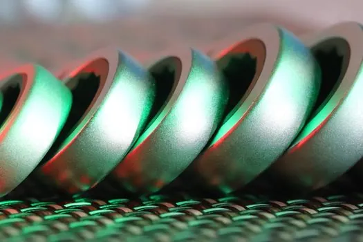
The rolling elements are frustum-shaped (truncated-cone) rollers, and the projections of the roller axes, the cone raceway, and the cup raceway all meet at a common point on the bearing axis, which is what makes the motion truly coaxial and prevents sliding between the roller OD and the raceways [S3][S5][S6]. This line contact gives a wider load-bearing patch than the point contact of a ball bearing, so for the same load capacity a tapered roller bearing can be smaller than a ball bearing, and it can carry both radial and axial loads simultaneously rather than just one [S3][S4]. The half-angle of the taper sets the ratio of radial to axial capacity: a steeper angle pushes more of the rated capacity toward axial load, which is why steep-angle designs are used on pinion shafts while standard-angle designs dominate general hubs [S2][S5]. For a closer look at how this radial-versus-axial split compares against another common bearing family, see the tapered roller bearing overview and the roller bearing reference pages.
Cage (retainer): roller spacing and cone-assembly handling
The cage, also called a retainer, sits between the rollers and the cone rib and has one job per surface: it keeps the rollers evenly spaced around the circumference, prevents them from tilting or skewing, and holds the cone assembly together as a single unit during handling before the cup is slid on [S2][S5][S7]. On most industrial and truck units the cage is a pressed or window-type steel or polymer piece riveted or snapped to the rollers, while some high-speed or sealed variants use a two-piece land-guided cage for cleaner lubrication flow [S1][S7]. A damaged or worn cage is one of the most common precursors to premature bearing failure because once a roller skews, the line contact breaks down into edge loading and the raceway spalls within a few hundred hours [S3]. Cage storage and handling is covered in the storage cage reference.
How the four parts work together: line contact, separable mounting, and pair loading
Because the cup and cone are separable, the axial clearance (end play) or axial interference (preload) is established during mounting by the axial position of the cone relative to the cup, not at the factory, and the installer can trade a few thousandths of an inch of clearance for life, stiffness, or thermal growth margin [S3][S5][S8]. Each individual bearing can only take axial load in one direction (the direction that pushes the rollers up the taper into the cone rib), so any application with bidirectional thrust uses two bearings mounted in opposing pairs, and the installer must set clearance on both bearings together [S2][S3][S7]. A typical heavy-truck wheel-end setup follows TMC RP 618, which calls for a final wheel-bearing clearance of 0.001 to 0.005 in after the spindle nut is torqued, and similar logic applies in railway axleboxes and gearbox pinion supports where controlled preload is mandatory [S4].
Selection criteria, common applications, and failure modes
Tapered roller bearings fit moderate-speed, heavy-duty applications with combined radial and axial load: gearboxes, differentials, wheel hubs, railroad axles, agricultural and construction machinery, and rolling-mill roll necks [S3][S4]. They are not the right pick for high misalignment (where spherical roller bearings, which share a similar line-contact load path, are the standard alternative) or for high-speed pure radial shafts (where cylindrical roller or deep-groove ball bearings usually win) [S3]. Common failure modes map back to individual parts: cone-rib wear under heavy thrust, cup raceway spalling from edge loading, roller skidding when preload is too light, and cage fracture when lubrication is starved or contamination reaches the pocket [S2][S3].
For the metrology side of confirming a suspect bearing, condition checks on a suspect bearing typically follow the workflow described in the checking and testing apparatus reference, and the typical host machines (cranes, wheel loaders, off-highway haul trucks) fall under the construction machinery and equipment category.
Trackable signals: ABMA/ISO 355 designation updates for metric series, supplier datasheet revisons for case-carburized pinion-grade bearings, and TMC RP 618 revisions for truck wheel-end clearance limits.
See also our earlier report, 304 vs 316 Stainless Scrap: Per-Kg and Per-Lb Price Snapshot, October 2026.