
Use a thermocouple, RTD, or thermistor as the temperature-sensitive element, then use a transmitter to turn its raw output into a standardized 4–20 mA or 0–10 V process signal.
The element determines sensing range, accuracy class, response, and thermal connection, while the transmitter determines excitation, linearization, compensation, isolation, and controller compatibility.
Separate the measurement element from the signal-conditioning stage
The sensing element belongs at the point of measurement. A thermocouple converts temperature into a small voltage, an RTD converts it into resistance, and
The transmitter is the interface between that raw sensor signal and downstream control equipment. It can excite the sensor, amplify low-level output, reject noise, apply sensor-specific compensation, and provide a standardized output such as 4–20 mA or 0–10 V [S1][S5].
This division matters because replacing a sensor with a transmitter does not replace the physical temperature detector. A transmitter still requires a temperature sensor input, while an accurate element connected to poor conditioning can produce a poorly resolved or unstable process value.
For applications where the sensing and conditioning functions are being separated architecturally, compare the temperature sensor selection against the temperature transmitter input specification rather than treating them as interchangeable devices.
Compare the principal sensor types by signal and compensation
Thermocouple signals are commonly within ±80 mV, so a transmitter normally provides amplification and cold-junction compensation. The cold-junction block makes the thermocouple reference junction appear as 0°C during processing [S1][S3].
RTDs require excitation voltage, amplification, and filtering. Signal conditioning also compensates for lead-wire resistance, non-linearity, and self-heating effects [S1]. The RTD and PT100 choice therefore affects both the physical element and the transmitter configuration.
Thermistors also require current or voltage excitation. The stability and accuracy of that excitation influence the stability and accuracy of the measured temperature, while amplification and low-pass filtering make the output usable by a digital acquisition system [S1].
On signal magnitude, a thermocouple is the simplest raw input because it normally delivers millivolts without sensor excitation. An RTD or thermistor requires a controlled excitation source, but its resistance-based input can support stable digital conversion when lead resistance and excitation accuracy are handled correctly [S1][S2].
For a direct instrument interface rather than a process transmitter, a signal calibrator is used to inject and measure test signals, whereas a transmitter conditions a live sensor input for control-system use.
Select by range, accuracy, response, and installation
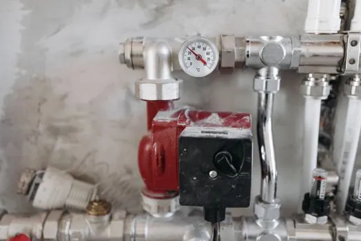
Specify the sensing element first against the process range, required measurement uncertainty, thermal mass, response time, and mounting method. The transmitter cannot recover spatial temperature gradients, improve sensor thermal response, or remove an unsuitable thermowell. [S3]
Use a thermocouple where the installation needs broad temperature coverage, long thermocouple leads, or a compact junction-type element, subject to the selected type’s specified range and tolerance. Use an RTD where repeatable resistance and stable moderate-range performance are required, with lead resistance included in the accuracy budget. Use a thermistor where its nonlinear resistance characteristic provides useful sensitivity over a restricted range and the transmitter can linearize that characteristic [S1][S5].
Set the transmitter span around the required process range rather than using an unnecessarily broad span. Industrial temperature transmitters accept thermocouple, RTD, and low-level sensor inputs and convert them to 4–20 mA, 0–10 V, or other DC outputs [S3].
The element and transmitter must agree on sensor type, engineering units, range, and wiring method. A temperature switch may be preferable for a discrete limit function, while a transmitter is preferable when the PLC or monitoring system needs a continuously variable measurement.
Match output and integration to the control system
A 4–20 mA transmitter is the practical default for long-distance industrial process measurement because it converts the sensor signal into a standardized current for transmission with limited loss and interference [S5]. A 0–10 V output can be suitable for shorter links or systems designed specifically for voltage inputs, but the receiving equipment must match the voltage range and grounding arrangement [S5].
For a 4–20 mA installation, verify the loop power, receiver input resistance, maximum cable length, and output burden before ordering. Use a temperature recorder or data logger when historical trending or multi-channel evidence is required, rather than replacing the transmitter with a logger that cannot accept the selected sensor input.
Understand accuracy, noise, and failure modes

The practical accuracy error combines the sensor element, transmitter electronics, cold-junction reference for thermocouples, lead resistance for RTDs, excitation error, installation effects, and input-output calibration. Therefore, selecting a transmitter accuracy figure without the sensor specification gives an incomplete system estimate. [S1]
Electrical noise can obscure small temperature changes, so filtering is part of measurement quality rather than optional housekeeping. Thermocouple conditioning requires amplification because the raw voltage is too small for many process instruments to record reliably, while RTD and thermistor channels require excitation as well as filtering [S1].
Common failure mechanisms include incorrect sensor type or wiring, insufficient loop power, excessive lead resistance, unresolved thermocouple millivolts, poor grounding, unprotected transients, and operation outside the sensor or transmitter range. Isolated conditioners reduce ground-loop and transient exposure but do not correct a physically misplaced or unstable temperature element [S2][S3].
For thermocouple installations, cold junction compensation inside a temperature transmitter explains the reference-junction stage that must be included in any independent thermocouple accuracy calculation.
Apply the recommendation by application
For a heated vessel with a continuous process-control output, use an RTD element when its range and response suit the process, and select a configurable transmitter with RTD input, lead-resistance compensation, linearization, and the required 4–20 mA output. [S3]
For a high-temperature process or a compact junction installation, use a thermocouple with a transmitter providing cold-junction compensation, thermocouple linearization, low-level amplification, and filtering. For a restricted-range test point where high resistance change is useful, use a thermistor with a transmitter that provides stable excitation and characteristic-based linearization [S1].
Do not specify a transmitter for a measurement that needs only switching, or an RTD/thermocouple as a complete field instrument when downstream equipment requires a standardized current output. The correct package is the sensing element, the connection accessories, the transmitter, and the receiving device working as one calibrated channel.
Before purchase, record the required temperature range, element type, accuracy, response time, output format, loop power, isolation requirement, sensor lead length, and hazardous-area classification, then verify each value against the manufacturer datasheet for the selected element and transmitter.