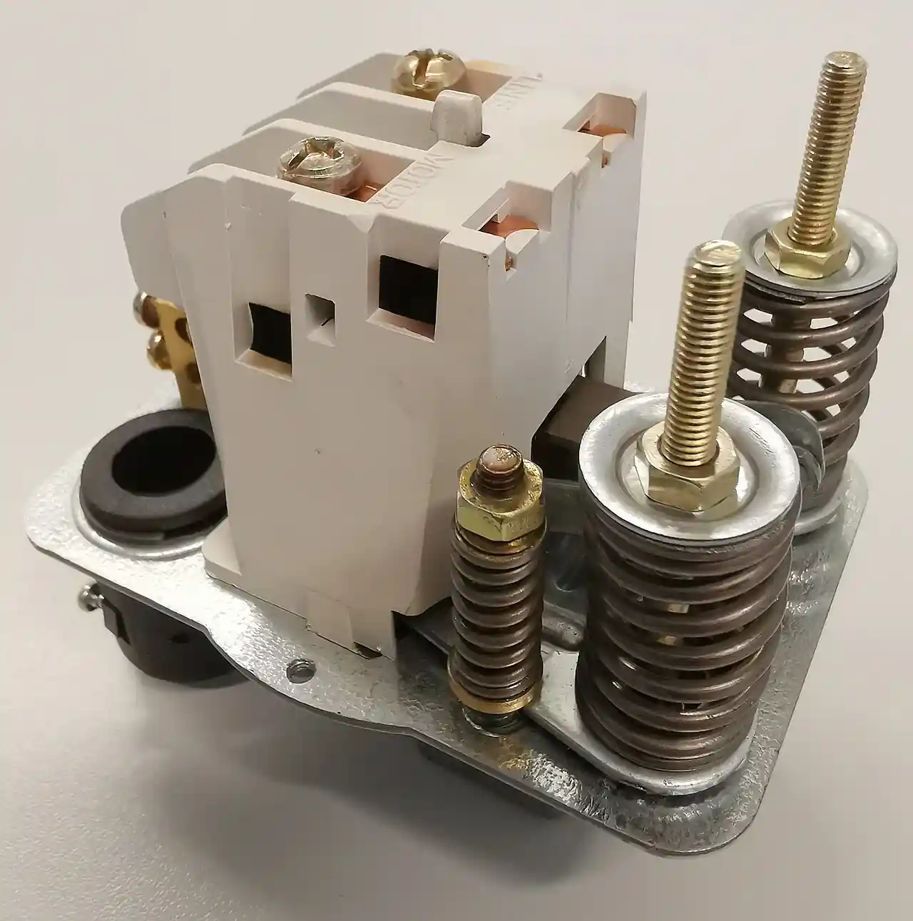
A temperature switch is an electromechanical device that opens or closes an electrical contact when the temperature at its sensing element crosses a setpoint. It has two functional parts: a thermal element, either a bimetallic strip or disc or a fluid filled bulb and capillary, and a snap-action switch that transfers its contacts decisively rather than creeping between states. Sensing spans run from roughly minus 50 to plus 400 deg C for bimetal elements and wider for gas filled systems, with remote bulb sensing over capillaries to 15 m, deadbands of 1 to 4 percent of span, and contact ratings of 5 to 15 A at 120 or 240 V AC. The shorthand temp switch appears all over plant drawings and is the same device.
What this page settles is the discrete protection layer: the overtemperature alarm, the two-position control step, and the hardwired safety cutout that must act when everything with a power supply and a program has failed. The purchase decision resolves into an RFQ line set, element type, span, setpoint placement, deadband, contact rating and reset action, enclosure and approvals, and each chapter feeds that line set with the numbers a supplier must quote against. The instrument is small and inexpensive, which is exactly why it is specified carelessly; a switch that trips 20 deg C late or welds its contacts shut on the one day it matters is not a bargain at any price.
This page treats the temperature switch as a purchasing object: how bimetal, vapor charged, and gas filled elements actually move a contact, what deadband and repeatability numbers mean on a datasheet, which enclosure and approval rows a plant RFQ needs, and how the hardwired interlock layer is specified so it stays independent of the control system. It is written for engineers who issue purchase specifications, not for readers who want a brochure summary.
Chapter 1 / 06
What a Temperature Switch Is and What Is Being Decided
A temperature switch is a two-part machine. The thermal element converts temperature into mechanical displacement: a bimetal curls as it warms, or a fluid filled bulb raises pressure through a capillary into the switch head. The snap-action switch converts that displacement into a clean contact transfer, so the output is not a signal to be interpreted but a state to be wired: closed below the setpoint, open above it, or the reverse. In family terms this is the thermal sibling of the pressure switch, the same housings, the same microswitch blocks, the same conduit entries, with a thermal element replacing the pressure Bourdon, which is why the two share catalogs, spare parts, and selection literature such as the Ashcroft eight-step guide cited in the sources.
In instrumentation taxonomy the device is the discrete cousin of the continuous temperature sensor: a sensor with a transmitter produces a reading, a switch produces an event. That distinction is the purchase decision. The plant buys this instrument when something must happen at a temperature: an alarm sounds, a fan starts, a burner is cut, a trip string opens. Three duties cover the field. Alarm duty announces a threshold to an operator or a monitoring system. Two-position control duty starts and stops fans, valves, and trace circuits around a band. Safety cutout duty removes energy on overtemperature and holds that state until a person attends to it, which is where manual reset versions earn their keep. The RFQ must state which duty applies, because it decides reset action, listing class, and how much of the datasheet matters.
The switch earns its place in panels rather than standing alone. A machine protection panel typically carries a flow switch on the pump discharge, a level switch on the lube oil reservoir, and a temperature switch on the bearing return, each hardwired into one protection string. The continuous layer sits beside it: a pressure transmitter reads the discharge line continuously for trend and soft indication, while the discrete layer holds the authority to trip without asking anything. The two layers fail differently, are tested differently, and are specified differently, and the panel drawing that confuses them usually discovers the difference during a trip investigation.
The hardwired property deserves its own paragraph because it is the reason the device survives in an instrumented world. The sensing element needs no power supply: temperature itself supplies the mechanical energy to move the contact, and the only current in the device is the load current it switches. There is no analog input, no excitation, no software between the process and the contact, and burner management systems and trip circuits are built to accept exactly that dry contact. Failure modes are visible and testable: a broken element fails in a defined direction, a welded contact fails discoverable by test, and chapter 6 covers how both are proven on schedule. Where continuous measurement and soft limits fit, the comparison belongs to the selection chapter; the protection argument stands on its own.
What is being decided, concretely, is a line set: element type and span, setpoint and where it sits in the span, deadband, contact configuration and rating, reset action, enclosure, approvals, and the mounting and capillary hardware that connects the element to the process. The chapters that follow give each line its numbers: chapter 2 the element physics, chapter 3 the construction families, chapter 4 the datasheet rows, chapter 5 the selection logic and RFQ language, and chapter 6 the installation, calibration, and failure discipline that keeps a cheap device trustworthy for decades.
Chapter 2 / 06
How the Snap-Action Element Works
The bimetal element bonds two metals with different expansion coefficients, a low expansion alloy against a high expansion steel, into one strip. Warm the strip and one side grows more than the other, so the strip curls; cold and it curls back. Wound into a helix it produces rotation proportional to temperature, which turns an adjustment cam against the switch lever; stamped into a disc it holds a slight dome until thermal stress snaps it through center at a repeatable temperature. The disc form is the cheaper, faster architecture and the helix the more precise adjustable one, and both make the bimetal simultaneously the temperature sensor and the actuator: there is no intermediate transduction to drift. Practical spans run roughly minus 50 to plus 400 deg C, with the snap disc covering the common band and special alloys extending each end.
The vapor charged bulb and capillary moves the measurement away from the wiring. A bulb at the process holds a volatile liquid together with its own vapor; the vapor pressure follows the saturation curve of that fill, steeply and repeatably, as bulb temperature changes. The capillary, a small bore tube typically to 15 m long, carries that pressure to a diaphragm or Bourdon element in the switch head, and the element actuates the same snap-action microswitch the bimetal would. Because the vapor pressure is set by the bulb, swings at the case and along the capillary contribute little, which makes this the preferred remote element on hot equipment. The bulb installs directly into the process, or into a thermowell when the line is pressurized, abrasive, or must stay sealed during element replacement.
The gas charged system fills the bulb, capillary, and element with nitrogen at a fixed charge. Gas pressure follows the ideal gas law with total temperature of the whole fill, which means the capillary and the case contribute to the reading as well as the bulb, so makers add bimetal compensation to subtract the case contribution. What the gas system buys is span: minus 180 to plus 400 deg C class ranges are catalog items, covering cryogenic and high temperature duty no vapor fill serves, and averaging bulbs, long sensing elements threaded through a duct, integrate temperature along their length for air and gas streams. The price is a wider deadband tendency and the compensation subtlety, which is why the selection chapter insists the case ambient be stated on the datasheet.
Mercury in steel systems, a bulb and capillary with a mercury column acting on the element, were once the precision choice and remain in old plants. They work, but mercury puts a regulated toxic metal into a device that will eventually be mishandled, and modern vapor and gas fills equal their practical accuracy. A new purchase should not specify them, and a replacement retrofit is the natural moment to retire them; state that requirement explicitly in the RFQ so a supplier does not quote the legacy item from habit or stock.
The snap-action microswitch is where mechanics become an electrical decision. A leaf spring carries the moving contact over center, so transfer happens in milliseconds with a small wiping motion that cleans the contact faces; this is what distinguishes a snap-action switch from a slowly transferring limit contact that arcs its way to failure. The standard form is SPDT, common plus normally open and normally closed, with resistive ratings of 5 to 15 A at 120 or 240 V AC. Inductive loads, motor starters and solenoids, must be derated two to three times or protected with a snubber, because breaking an inductive current forces an arc that welds silver alloy contacts. Contact materials are silver tin oxide and its relatives, chosen to survive the arc energy of the declared duty.
Deadband, also called differential, is the temperature distance between trip and reset, and it is set mechanically by the gap between the operating point and the reset point of the lever system, often with an adjustable differential spring. Typical values are 1 to 4 percent of span, fixed or adjustable. Repeatability, the spread of the trip point over many cycles under identical conditions, runs 1 to 2 percent of full scale on industrial grades. Note what the device does not need: no cold junction reference like a thermocouple circuit, no excitation current like a resistance thermometer, no signal conditioning at all. The only electricity in the instrument is the load current it exists to break, and that simplicity is the specification's greatest asset and its greatest temptation to cheap out.
Chapter 3 / 06
Construction, Enclosures, and Duty Boundaries
The housing is the part that survives the plant. Standard cases are powder coated die cast aluminum, with 316 stainless cases for corrosion, washdown, and offshore duty. Enclosure ratings follow the NEMA families: NEMA 4 and 4X for weather and hose-down, and NEMA 7 and 9 for Class I and Class II hazardous locations, with ATEX and IECEx flameproof Ex d certifications carrying the same duty in international markings, all built to the IEC 60079 series. Conduit entries are threaded for glands or hubs, terminations are screw terminals on a marked block, and gaskets and window options exist for setpoint visibility without opening the case. A window sound trivial until the first commissioning night shift.
Setpoint hardware separates two purchasing philosophies. The adjustable form has an external scaled dial or an internal screw with a lock nut, and it suits process duty where the band will be tuned on the machine. The factory set form is calibrated and lead sealed by the maker at a stated point, and it suits safety cutout duty where nobody should adjust anything at two in the morning; the seal is the audit trail. Dual setpoint heads carry two independent stages in one enclosure, alarm plus trip or alarm plus fan start, each with its own element coupling and contacts. Manual reset versions latch the tripped state mechanically, a lever or pushbutton restoring them, which is the standard construction for furnace and oven high limits.
Wetted and mounted hardware decides whether the element lives long enough to matter. Bulbs come as plain elements in 316 stainless or copper alloy, as averaging bulbs for ducts, and with armor: stainless braided capillary or full flexible conduit, because an unprotected capillary is a waiting casualty. Lengths are catalog options to 15 m; a capillary must never be kinked and never spliced, since a kink restricts the fill and a splice is a repair that does not exist in this technology. Union and compression fittings mount the bulb, and a protective well carries it in pressurized or flowing lines. The element table below fixes the duty boundaries between the families.
Sensing element
Sensing span class
Reach
Character
Natural duty
Bimetal disc or helix
minus 50 to plus 400 deg C
Local only, element in the case
Fixed or adjustable, vibration sensitive
Ovens, surfaces, machine mounted alarms
Vapor charged bulb and capillary
minus 35 to plus 280 deg C depending on fill
Remote, capillary to 15 m
Steep actuation across the chosen span, case ambient barely matters
Vessels, pipes, bearing housings, hot equipment
Gas charged bulb and capillary
minus 180 to plus 400 deg C class
Remote, capillary to 15 m, averaging forms
Wide span, needs ambient compensation
Cryogenic duty, wide range, duct averaging
Mercury in steel
legacy catalog spans
Remote
Legacy precision, regulated fill
Avoid in new purchase, plan retirement at retrofit
Boundaries are worth stating as bluntly as the table. A temperature switch is not a measurement: it reports one bit at one point, and nothing between trips. It is not fast: thermal mass and capillary fill put the event seconds to tens of seconds behind the process, which is fine for protection and useless for control loops. It is not a fire safety device, and chapter 5 draws that line explicitly. And it is not self diagnosing: a welded contact looks exactly like a healthy one until the trip test, which is why the maintenance chapter puts the trip test on a calendar with a name attached.
Chapter 4 / 06
Key Specification Parameters
The table below lists the datasheet rows that decide whether a quotation matches the service. Values are typical industrial grades: certified safety versions state tighter figures, and the cheapest catalog items state almost nothing, which is itself information. The paragraphs after the table treat the two rows most often misused, setpoint placement and contact rating.
Attribute
Typical range or options
What it decides
Element and span
bimetal minus 50 to plus 400 deg C; vapor fills minus 35 to plus 280; gas fills minus 180 to plus 400 class
Which physics serves the duty and where the range limits sit
Setpoint adjustability
external scaled dial, internal screw with lock, factory set and sealed
Commissioning access against tamper resistance and audit trail
Deadband
fixed or adjustable, typically 1 to 4 percent of span
Cycling behavior and how close reset sits to trip
Repeatability
1 to 2 percent of full scale, industrial grades
How tight the protection band actually is
Sensing reach
local bimetal, or bulb with capillary to 15 m
Where the head can sit relative to heat and vibration
Corrosion acceptance and mechanical survival of the line
Contact rating
SPDT 5 to 15 A at 120/240 V AC resistive, inductive derate 2 to 3 times
What the switch can break without welding or arcing out
Enclosure
NEMA 4, 4X, 7, 9; IP66 and IP67 equivalents
Weather, washdown, and hazardous area survival
Approvals
UL listed limit control, CSA, ATEX and IECEx Ex d
Safety listing class and area acceptance
Case ambient limits
minus 40 to plus 65 deg C typical at the head
Case temperature error for gas fills and electronics free survival
Vibration tolerance
per datasheet, snap disc forms most sensitive
Mounting strategy and element choice on rotating equipment
Setpoint placement is the row that quietly decides accuracy. Catalog accuracy and repeatability are graded over the span, and both degrade near the ends: a setpoint crowded against the range limit inherits the worst of the span plus the least adjustment room. The working practice, formalized in the Ashcroft selection guide, is to place the setpoint in the middle third of the range, which also leaves headroom for process excursions and for the deadband to act. By the same logic, do not buy a wide range for a narrow duty: a 0 to 400 deg C span holding a 45 deg C setpoint spends 90 percent of its span as error budget. Pick the nearest narrow span whose limits bracket the process with margin.
Contact rating is the row that decides whether the switch survives its own success. The resistive rating, 5 to 15 A at 120 or 240 V AC, applies to heaters and lamps; motor starters, contactor coils, and solenoids are inductive and must be derated two to three times or protected with an RC snubber or a varistor across the load, because the induced voltage at break sustains the arc that welds contacts. State the actual load in the RFQ, current and type, and let the supplier size the protection. In the panel the discrete contact lands on the same terminal strip as the 4 to 20 mA loop from a pressure transmitter, and the two circuits must be kept apart: segregation and correct conductor sizing keep a 10 A trip circuit from inducing nuisance noise into a millivolt level analog channel.
The options table below compresses the circuit, reset, and enclosure choices into the form a specification meeting can argue from.
Option
Typical form
What it buys
SPDT single stage
Common plus normally open and normally closed
Alarm and trip from one element with fail direction choice
Dual setpoint two stage
Two independent stages in one enclosure
Alarm plus fan start, or alarm plus trip, without two housings
Manual reset latch
Lever or pushbutton, trips and holds
Overtemperature cutout that demands human attendance
Adjustable deadband
Differential spring or external screw
Reset behavior tuned against process oscillation
Gold plated contacts
Dry circuit rating class
Reliable switching of low voltage logic inputs
NEMA 7 or 9 Ex d case
Flameproof enclosure with certified entries
Class I and Class II areas, ATEX and IECEx zones
Scaled window or local indication
Window on the dial, or flag indication
Setpoint visible without breaking the enclosure seal
Chapter 5 / 06
Selection Decision Factors and RFQ Language
The selection sequence distills the vendor eight-step practice into a checklist a specifier can run in one meeting, and each step eliminates a class of quotations.
Classify the duty: alarm, two-position control, or safety cutout; the class fixes reset action, listing, and evidence demanded.
Place the setpoint in the middle third of the narrowest catalog span that brackets the process with margin.
Decide adjustable against factory set: adjustable for process tuning, factory sealed where audit and tamper resistance rule.
Size the deadband against the process: narrow enough to reset promptly, wide enough that an oscillating line does not chatter the contact.
Choose local against remote sensing: bimetal where the case can sit at the measurement, bulb and capillary to 15 m where heat, vibration, or access say otherwise.
Fix the wetted hardware: 316 bulb for corrosion, averaging bulb for ducts, armor for the capillary route, a protective well in pressurized lines.
State the case ambient honestly, because gas filled systems compensate against it and every datasheet assumes a stated range.
Specify the circuit: contact configuration, the actual load with its inrush and inductance, snubber provision, and the fail-safe direction, open on trip for de-energize to trip strings.
Applications map onto that checklist quickly. Bearing and winding overtemperature alarms on pumps, compressors, and conveyors want a vapor bulb at the bearing with the switch head mounted off the machine, so vibration reaches the bulb and not the contacts. Furnace and oven high limits want a factory set point with manual reset, wired so the cutout interrupts the burner circuit itself, not merely an alarm output. Transformer duty wants the dual setpoint two stage form: first stage starts fans, second stage alarms or trips, one housing doing both jobs. Heat trace cut-in, cooling water valve two-position control, and dryer door interlocks are classic adjustable band duty. And the emergency shutdown layer wants the switch wired in series in the trip string, hardwired, so that a PLC failure cannot defeat the limit no matter what the software was supposed to do.
Two neighbors are not this device, and the RFQ should keep them straight, because the comparison belongs here rather than anywhere earlier. One is the room thermostat: an HVAC two-position device built for wall mounting, narrow differential, low current pilot duty, comfort control in occupied spaces, a different instrument with a different listing world, and specifying a thermostat into an industrial trip string is a category error. The other is the analog route: a temperature transmitter carrying an RTD PT100 or thermocouple input feeds the control system continuously, and limits become software alarms, soft limits with configurability, trend, and diagnostics, but they depend on the transmitter, the input card, the power supply, and the PLC program all being alive at the moment of the excursion. The layering argument is not either or: the analog layer, a temperature transmitter feeding the control system, covers trend and early warning, and the hardwired temperature switch keeps the trip authority for the day the control system is down or wrong. Defense in depth buys one of each and wires them independently.
The fire safety boundary is its own line because it appears in specifications that should know better. A temperature switch is a process device: it acts on process temperature, to protect equipment and pipe. A heat detector is a fire alarm device, listed for that service, responding to heat from a fire in occupied spaces and reporting to the fire alarm panel; a heat detector belongs on ceilings and in ducts under fire codes, not on bearing housings. Neither substitutes for the other: the process switch is not listed for fire detection, and the fire device does not trip process equipment. Write each into its own specification and never swap them to save a purchase order line.
Vibration closes the selection logic because it kills more of these devices than temperature does. Snap discs chatter under vibration, contacts arc, and fatigue cracks the bimetal; on rotating equipment the standard answer is remote sensing, the bulb at the measurement and the head on a stationary surface, with the capillary isolating the mechanics. Where even the bulb route is marginal, state the vibration spectrum in the RFQ and expect the supplier to qualify the offering or decline it honestly. Contact protection belongs in the same paragraph: every inductive load gets its snubber or varistor at commissioning, not after the first welded contact, and the trip test calendar in chapter 6 is what proves the protection worked.
Application
Construction to specify
Check before order
Bearing overtemperature alarm, pumps and compressors
Vapor bulb at the bearing, head off the machine, SPDT to the alarm string
Bulb contact quality, capillary route, load rating of the alarm relay
Furnace or oven high limit cutout
Factory set point, manual reset, UL listed limit control in the burner circuit
Setpoint in middle third of span, burner interlock wiring reviewed
Transformer alarm with fan start
Dual setpoint two stage, first stage fans, second stage alarm or trip
Stage separation and motor load rating with inrush
Heat trace cut-in and high limit
Adjustable span around maintain temperature, weatherproof case
Deadband against trace cycling, ambient rating at the case
Cooling water two-position valve control
Bulb in the line, adjustable deadband, SPDT valve duty
Deadband wide enough to stop valve hunting
Machine protection panel interlock
SPDT in the trip string, de-energize to trip, lockable setpoint
Fail-safe direction proven by test, contacts sized to the string
Hardwired overtemperature layer for a control system
Manual reset high limit in series with the trip circuit, independent wiring
Independence from controller power and I/O, listed wiring practice
A complete RFQ block reads: quantity; duty class stated as alarm, control, or safety cutout; element type with span; setpoint value with its placement in the span; deadband fixed or adjustable with the value; bulb length, capillary length and armor, and well requirement with material; contact configuration with the actual load current, voltage, and load type plus snubber provision; reset action; enclosure rating and hazardous area certification with zone and group; case ambient range at the mounting point; and the acceptance evidence, calibration certificate for the setpoint and a functional trip test at witnessed handover. A quotation that answers the setpoint row with a range and a shrug is incomplete at any price.
Chapter 6 / 06
Installation, Standards, Failure Modes, and Maintenance
Installation quality starts at the bulb. A bulb in a thermowell must fit the bore and carry thermal contact paste; an air gap around the bulb is insulation, and a sloppy fit can add tens of seconds of lag and a real offset at trip, which is a protection margin spent on nothing. Direct immersion bulbs seat to depth with their union fittings. The capillary routes with a generous bend radius, protected in armor or conduit along its whole run, never kinked and never spliced, and away from hot surfaces that could heat a gas fill. The head mounts on the stationary side of vibration, out of radiant heat, with the orientation the datasheet states, because some mechanisms are gravity sensitive. Hazardous area entries get their certified glands and seals; the Ex d enclosure is only as valid as its weakest entry.
Wiring practice decides the fail direction. The protection convention is de-energize to trip: the normally closed contact opens on high temperature, so a broken wire or lost supply produces the trip state rather than hiding behind a live signal. Alarm duty can close on trip where the logic and the risk analysis accept it, but the direction must be a written decision, not a terminal accident. Every inductive load gets its RC snubber or varistor, sized at commissioning. Where the contact runs into an intrinsically safe circuit, a safety barrier limits the fault energy that can reach the hazardous area; the barrier and the switch form one evaluated system, and the safety barrier datasheet states the allowed cable capacitance and inductance the loop design must respect. Segregate the trip wiring from analog channels, torque the terminals, and record the as-left setpoint and deadband in the loop file.
Standards and listings frame what the certificates mean. Safety cutout duty in North America is carried by UL listed temperature limit controls and CSA certification, which is the listing class burner management and inspection bodies recognize; a switch without the listing is not interchangeable with one that has it, whatever the range says. Hazardous area versions carry ATEX or IECEx certification built on the IEC 60079 series, with the Ex d flameproof concept marking, zone, and gas group on the nameplate. Enclosure ratings follow the NEMA and IP families quoted in chapter 3. None of these markings replaces the functional trip test; they define what the manufacturer built, and the test defines what your plant received.
Calibration is a two-point event on a calendar. The field tool is a dry block temperature calibrator: pull the bulb or the element, insert it with the certified reference, an RTD PT100 probe or a calibrated thermocouple, into the same well, and ramp the block through the setpoint from both directions. Record the trip and reset temperatures, compute the deadband, and compare the pair against the loop file and the maker's tolerance; a setpoint that has walked more than the tolerance comes off the line for adjustment or replacement. A dry block temperature calibrator with a certificate of its own keeps the evidence chain intact. Safety cutout switches get the test every year or every turnaround, whichever comes first; alarm and control duty typically follows the site instrument round at the same interval as the rest of the panel.
Failure modes follow a short and predictable list, and the table pairs each with the symptom that exposes it and the practice that prevents it.
Failure mode
Symptom in service
Prevention
Contact welding from inductive load
Load will not drop out on trip, or trips and re-closes
Snubber or varistor at commissioning, correct rating, scheduled trip test under load
Capillary strike, kink, or charge loss
Indication shifts in one direction or the switch freezes one state
Armor and conduit protection, no splices, treat any strike as a failed unit
Bimetal fatigue and drift
Trip point wanders between annual tests
Two-point calibration check, replace on drift beyond tolerance
Setpoint screw migration under vibration
Setpoint reads different after service or season
Lock nut and seal wire, setpoint recorded in the loop file after every touch
Correct enclosure rating, sealed entries, inspection on the instrument round
Maintenance is a named calendar, not an intention. The annual round trips every safety switch under real load and proves the direction: trip it, watch the string respond, restore it, sign it. The same round can test the flow switch and the level switch in the same panel, since the protection string is only as good as its least tested member, and it should re-verify setpoints against the records. Spares strategy borrows from the pressure switch inventory the devices share families with: common elements, common contacts, a sealed shelf spare for every critical span. Exercise long-stored spares before use, because contacts corrode in the box too. None of this costs a tenth of one unplanned stop, and every entry becomes the evidence that the cheap device in the trip string was never the weak one.
FAQ
Where should the setpoint sit within the switch range?
In the middle third of the span, which is the placement the Ashcroft selection practice formalizes. Accuracy and repeatability are graded across the full range and degrade near both ends, so a setpoint crowded against a limit inherits the worst performance and the least adjustment room. The middle third also leaves headroom for process excursions and for the deadband to operate without running off scale. By the same logic, choose the narrowest catalog span that brackets your process with margin.
When do I need bulb and capillary instead of a bimetal element?
Whenever the measurement point and the wiring point cannot be the same place. A bulb and capillary senses remotely over distances to 15 m, keeps the switch head away from heat, vibration, and access hazards, and lets the bulb sit in a protective well for pressurized or abrasive lines. Bimetal elements sense only where the case sits, which is right for ovens, surfaces, and machine mounted alarms where local indication and adjustment are wanted. Choose remote sensing whenever rotating equipment vibration would reach a snap disc.
What deadband should I choose?
Typical industrial values run 1 to 4 percent of span, fixed or adjustable. Too narrow and an oscillating process chatters the contact, arcing it toward failure and alarming operators into ignoring the alarm; too wide and the process sits far past the reset point before the state changes back. Size the deadband against the process dynamics: a smooth heating loop tolerates a narrow band, while a two-position valve on a stirred line needs width to stop hunting. State the required value in the RFQ, not whatever the factory sets.
Should the contact open or close on trip?
For protection strings, open on trip, which is the de-energize to trip convention: the normally closed contact breaks when temperature rises, so a broken wire, a lost supply, or a cut cable produces the safe state instead of hiding behind a live signal. Alarm duty can close on trip where the logic accepts the failure direction, but that must be a written decision in the loop design, not an accident of terminal choice. Whatever the direction, prove it by functional test at commissioning and again on the annual round.
Manual or automatic reset after an overtemperature trip?
Manual reset for safety cutouts, automatic reset for alarm and control duty. A manual reset latch holds the tripped state until a person attends to it, which is the standard construction for furnace and oven high limits: you want the burner locked out until someone finds out why. Automatic reset suits fan start, valve control, and alarm annunciation, where the process should recover on its own. Dual stage housings can mix the two, an automatic alarm stage and a manual trip stage, which covers most machine protection panels.
How do I verify a setpoint in the field?
Pull the sensing element, put it in a dry block temperature calibrator together with a certified reference probe, and ramp the block through the setpoint from below and from above. Record the trip and reset temperatures, compute the deadband, and compare both against the loop file and the maker tolerance. A setpoint that has walked beyond tolerance comes off the line for adjustment or replacement. Safety cutout switches earn this test every year or every turnaround, whichever comes first.
What enclosure and approvals does a plant switch need?
Outdoor and washdown areas want NEMA 4 or 4X, and their IP66 or IP67 equivalents. Hazardous locations want NEMA 7 or 9, or the international ATEX and IECEx flameproof Ex d marking with the zone and gas group stated on the nameplate. Safety cutout duty additionally wants the listing class the inspection body recognizes, UL listed temperature limit controls or CSA certification in North America. An unlisted switch with the right range is not a substitute for a listed one in a burner circuit, whatever the price difference.