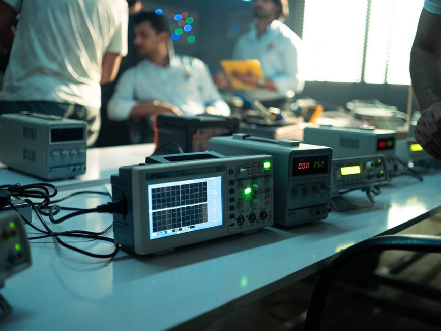
A multimeter test lead set is a passive accessory pair — typically silicone-insulated, rated to 1000 V CAT III / 600 V CAT IV, with 4 mm banana terminations and exposed probe tips or screw-on alligator clips — designed to carry a voltage or current signal from a test point back to a measuring instrument with minimal disturbance [S2].
A spectrum analyzer is an active superheterodyne or FFT receiver that downconverts and resolves RF energy across a frequency span, with bench instruments such as the Keysight E4408B ESA-L covering 9 kHz to 26.5 GHz at 1.1 dB overall amplitude accuracy and 100 Hz to 5 MHz RBW before being marked obsolete and superseded by the N9000B CXA [S4].
Core Function: Voltage Conductor vs Frequency-Domain Receiver
The defining job of a test lead is galvanic coupling: a 1.2 m to 1.5 m silicone-jacketed conductor with 4 mm shrouded banana plugs at the instrument end and a 2 mm tip at the probe end, hand-built in modular families (retractable shrouds, plunger-style clips, TL175-style silicone leads) so the same pair can be reconfigured for DMM, oscilloscope, or power-quality use [S2].
The defining job of a spectrum analyzer is frequency-domain measurement: a calibrated receiver that displays power (dBm) versus frequency (Hz), with internal routines for phase noise, noise figure, and pulsed-RF measurements that would otherwise require a phase detector, a low-noise reference source, and a math stack [S1]. Phase noise is one of the most common production tests because poor oscillator phase noise degrades data-link bit error rates, increases adjacent-channel interference, and breaks telecom timing margins [S1].
Decision Criteria: What You Are Actually Measuring
Pick a test lead when the question is a scalar value at a single point in time — line-to-neutral voltage at a 480 V panel, resistance of a motor winding, continuity of a safety ground, or the DC output of a 24 V power supply. SureGrip-style leads with retractable shrouds and modular alligator clips are the typical modular accessory family published by Fluke for industrial and automotive service [S2].
Pick a spectrum analyzer when the question is frequency-selective — harmonic content of a 2.4 GHz Wi-Fi PA, sideband spur hunt on a 700 MHz LTE local oscillator, or phase noise skirt at 10 kHz offset from a 100 MHz crystal. A bench analyzer with +7.5 dBm third-order intercept and 5-minute warm-up stability is the typical datasheet envelope for general RF work [S4].
Head-to-Head Comparison Across 4 Decision Criteria

<strong>Measurement domain:</strong> test leads are time-domain scalar (voltage, current, resistance) [S2]; spectrum analyzers are frequency-domain vector (power vs. frequency, phase noise) [S1].
<strong>Typical frequency range:</strong> test leads carry DC up to a few kHz of useful bandwidth before the lead capacitance and inductance distort the waveform; spectrum analyzers span 9 kHz to 26.5 GHz in a single bench instrument, with real-time and USB variants extending or shrinking that range [S4].
<strong>Calibration and accuracy class:</strong> a test lead is a passive accessory whose accuracy is set by the host DMM (e.g. 0.5% DCV on a handheld); a spectrum analyzer carries its own amplitude-accuracy spec, e.g. 1.1 dB overall amplitude accuracy, which becomes the dominant error term above the lead itself [S4].
<strong>Cost band:</strong> industrial test-lead sets are accessories in the tens-of-dollars range, often bundled with the meter; a 26.5 GHz bench spectrum analyzer is capital equipment in the five-figure range and historically sits on a calibration cycle of 12 months for amplitude and frequency reference [S4].
When Test Leads Are the Wrong Tool
Test leads cannot resolve frequency content: hooking a DMM lead to an RF output gives you the detector's average, not the 2.4 GHz carrier or its harmonics. Above roughly 100 kHz of edge speed, the lead's series inductance (~1 µH/m) and shunt capacitance (~100 pF/m) form a low-pass filter and ring on fast transients — the exact reason oscilloscope probes ship with matched passive or active compensation networks rather than bare banana leads. [S2]
Test leads also do not quantify distortion. A 1% THD + N figure on a 1 kHz audio source looks identical to a 0.001% THD + N figure on a DMM, because both are buried inside the meter's AC bandwidth. That distinction is only visible in the frequency domain on a spectrum analyzer or audio analyzer.
When a Spectrum Analyzer Is the Wrong Tool
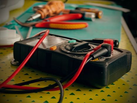
A spectrum analyzer is overkill — and the wrong physical interface — for troubleshooting a 24 V control loop, tracing a 120 V outlet to its breaker, or verifying thermocouple continuity on a heater band. Those tasks want a test leads kit with a CAT III 1000 V rating and shielded banana terminations, not a 26.5 GHz receiver [S2].
Equally, a sweep analyzer without a tracking generator cannot measure return loss, cable loss, or filter response in one shot — the typical workaround is a tracking-generator option or a separate vector network analyzer. And a free audio-band VST spectrum analyzer (e.g. DRAnalyzer from Bakuag, a VST3 plugin tagged Compressor / Spectral Analysis) only resolves the 20 Hz to 20 kHz band inside a DAW and has no hardware input at all [S3].
Standards, Sourcing, and Spec Boundaries
Test-lead safety classifications are governed by IEC 61010-031 for hand-held probe assemblies, with category ratings (CAT II / CAT III / CAT IV) and voltage ceilings (600 V / 1000 V) printed on the shroud — a 1000 V CAT III / 600 V CAT IV silicone lead is the typical industrial service rating [S2].
Spectrum-analyzer specifications follow manufacturer datasheet conventions: frequency range, resolution bandwidth (RBW) range, video bandwidth, displayed average noise level (DANL), third-order intercept (TOI), phase noise at a stated offset, and amplitude accuracy. A 1.1 dB overall amplitude accuracy, 100 Hz to 5 MHz RBW, and +7.5 dBm TOI after 5-minute warm-up is a representative mid-tier envelope, with the E4408B ESA-L now superseded by the N9000B CXA over the same 9 kHz to 26.5 GHz band [S4].
Field Practice: Keeping Both on the Bench
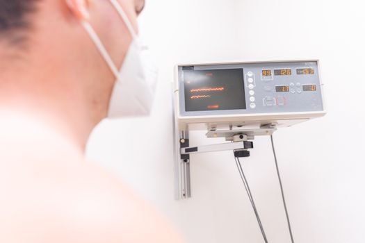
For an RF bench engineer the practical rule is: DMM with modular leads for power-supply rails, ground continuity, and bias points; oscilloscope probe for switching waveforms; spectrum analyzer for any signal above ~50 MHz or any place you need to see a spur, a harmonic, or a phase-noise skirt. The three overlap in the audio-to-low-MHz band, but outside that window the wrong tool costs hours. [S1]
Track for the next planning cycle: (1) any IEC 61010-031 amendment that reclassifies the CAT III / CAT IV voltage ceilings for hand-held probe assemblies, and (2) Keysight's N9000B CXA firmware revisions that extend phase-noise and noise-figure measurement routines inherited from the obsolete E4408B ESA-L platform [S4].
For component-level specifications, see gas analyzer.
For related coverage, see Industrial Refrigeration Smart Manufacturing: 2026 Spec Map.