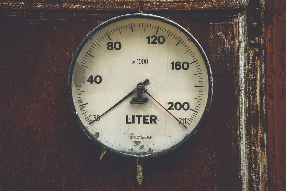
Thermal mass flow meters for liquids use heat transfer to determine mass flow, with sensor designs including inline, insertion, bypass, and hot-wire configurations. The design choice sets the balance between low-flow sensitivity, pressure drop, and installation complexity.
The most important distinction is not simply inline versus insertion. It is whether the liquid remains in thermal contact with the sensing elements, how much flow bypasses the sensor, and whether the application requires low-flow laboratory measurement or higher-capacity industrial service.
What Thermal Mass Flow Meter Sensor Designs Measure
Thermal mass flow measurement is based on heat transfer between a heated element and the flowing fluid. In thermal dispersion meters, flow removes heat from a heated velocity sensor, and the electronics measure either the resulting temperature difference at constant electrical power or the power required to maintain a constant temperature difference [S1].
The operating relationship includes fluid thermal conductivity, specific heat capacity, density, velocity, and heated-sensor diameter. Because these properties enter the measurement response, a meter calibrated for one fluid or gas composition cannot be assumed accurate for another without an appropriate calibration factor [S1].
Thermal mass flowmeters determine fluid flow through heat-transfer effects using either thermal-dispersion or calorimetric principles [S1].
Thermal dispersion and calorimetric designs are the two principal measurement families. Both are available commercially, but their installation geometry, sensitivity, and susceptibility to fluid properties differ substantially [S1].
Inline, Insertion, Bypass and Hot-Wire Configurations
Inline meters place the sensing assembly directly in the main flow passage, while insertion meters introduce a probe into an existing pipe. Bypass meters divert a controlled portion of the process flow through a smaller measuring channel, and hot-wire anemometers use a heated wire or film exposed to the fluid [S1][S5].
Insertion designs can be installed without removing the complete pipe run, but they require sufficient straight pipe and representative flow distribution around the probe. A thermal meter must see the actual process flow rather than a stagnant or distorted profile, so elbows, valves, pumps, and other disturbances can bias the result.
The measuring branch carries a sample of the main flow, and the relationship between bypass flow and total process flow depends on the geometry. Bypass and probe-type arrangements can also be used for larger-capacity flows where the inline sensor would be impractical [S4][S10].
Hot-wire anemometers are the classic thermal-dispersion form. The heated body loses heat to the moving fluid, and the measured electrical response is related to convective heat transfer.
Decision Criteria for Liquid Service
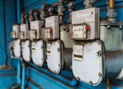
For low-flow liquid metering, an inline meter with an unobstructed path is a strong candidate when low pressure loss and reliable low-velocity measurement are priorities [S9]. For a compact installation, an insertion meter may be more practical, provided the manufacturer specifies the required straight-run arrangement and the probe is installed in a location with representative flow.
For larger flows or applications where a full-bore inline sensor would be costly, bypass designs can provide a practical path, but the bypass geometry and fluid properties become part of the measurement system. A probe-type design can also cover larger flows in ducts, flare stacks, and dryers, although liquid-service selection still requires compatibility with the fluid and line geometry [S4][S10].
The comparison below ranks the main configurations against the criteria that most often determine liquid-service suitability.
Accuracy for thermal mass flow meters is commonly broken into a percentage of reading and a percentage of full scale [S8].
Which Design Suits the Application?
Inline sensors are suitable when the liquid must pass through a dedicated measuring tube, the application includes low-flow control, and installation downtime is acceptable. They are less attractive for a straight pipe run where a compact retrofit is required or where even a small pressure loss is unacceptable. [S1]
Insertion sensors are suitable for monitoring and control in existing lines where a probe can be mounted in a representative section of pipe. They are not the natural choice for a laboratory cell that requires a specified unobstructed flow path, or for a line where upstream fittings leave insufficient straight length.
Bypass meters are suitable when the required capacity is high relative to a practical inline sensor or when the measurement branch provides a more manageable size. They require careful consideration of the bypass ratio and the fluid’s heat-transfer behavior; a bypass meter is not simply a smaller inline meter because the flow division adds another variable to the system [S1][S10].
Hot-wire anemometers are suitable for compact, low-flow, or specialized systems where sensitivity matters more than industrial installation convenience. They are less suitable as the default choice for a large, dirty, or high-maintenance liquid line unless the manufacturer has validated the sensor materials and geometry for that service [S5].
Materials, Pressure and Temperature Constraints
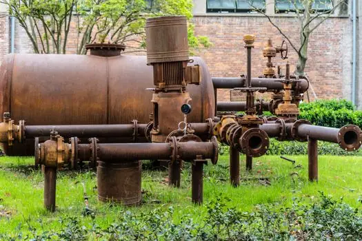
Liquid-service selection must begin with wetted-material compatibility and the operating envelope rather than with flow range alone. Thermal mass meters are available in high-pressure and high-temperature designs, and special constructions include glass, Monel, and PRA [S4]. These examples show why a generic “stainless steel” assumption is insufficient for corrosive or high-temperature service.
Pressure rating, temperature range, seal design, and the permitted fluid composition should be checked against the actual installation. Thermal mass measurement is less affected by changes in viscosity, density, temperature, or pressure than volumetric measurement, but the thermal response remains sensitive to properties that enter the heat-transfer relationship [S4][S1].
Dirty liquids, entrained solids, flashing liquids, and changing compositions require particular caution. A thermal meter with no moving parts can reduce maintenance compared with several mechanical technologies, but a stationary sensor is not immune to fouling or deposits [S5][S7]. The manufacturer’s application limits and calibration strategy determine whether the design remains valid after contamination or composition changes.
Installation and Commissioning Checks
Installation quality can determine whether a correctly selected sensor produces acceptable results. The flow should pass across the sensing element in the direction expected by the meter, and the sensing zone should not be occupied by an elbow, valve, pump discharge, or other disturbance unless the manufacturer explicitly permits that arrangement. [S1]
For insertion and probe meters, verify the specified upstream and downstream straight-run lengths before ordering. For inline meters, confirm pipe diameter, orientation, reducers, bends, and the physical clearance required to remove the sensor assembly. A thermal meter installed in a distorted flow profile can still have good laboratory accuracy while failing to represent process flow accurately [S1][S9].
Commissioning should include zero verification with the appropriate fluid conditions, comparison against a reference method, and confirmation of the configured fluid coefficient. For applications involving mixtures, confirm whether the factory coefficient represents the actual composition and whether a composition correction is required [S1].
Signal and installation requirements also matter. Examples in the cited product literature include 4–20 mA and pulse outputs, while liquid flow switches may use NO or NC NPN outputs with a user-adjustable setpoint [S4]. The output protocol, electrical supply, hazardous-area classification, and control-loop requirements should be fixed before the sensor construction is selected.
Practical Selection Sequence
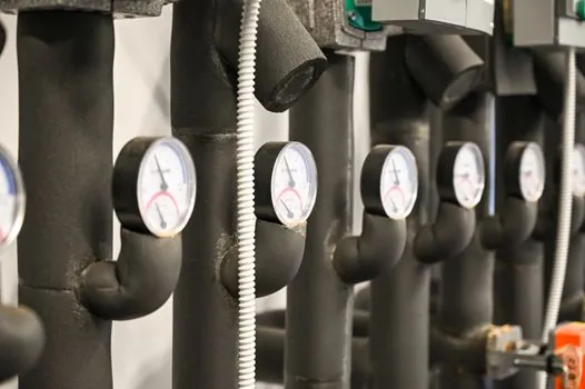
Start with the fluid list, including composition, viscosity range, temperature, pressure, density, specific heat, conductivity, and solids content. Then establish the required mass-flow span, minimum detectable flow, acceptable pressure loss, pipe size, and installation constraints [S1][S4].
Next, compare inline, insertion, bypass, and hot-wire designs against those requirements rather than against headline accuracy alone. A low-flow inline meter with an unobstructed path may outperform a more convenient probe arrangement in repeatability, while a bypass or insertion design may win where capacity or retrofit speed dominates [S9][S10].
Finally, obtain manufacturer confirmation of fluid compatibility, wetted materials, pressure and temperature ratings, straight-run requirements, output type, calibration method, and maintenance access. Track those documents during procurement because they define whether the selected thermal mass flow meter remains traceable to the actual liquid service.
For projects with changing liquid composition or demanding low-flow control, evaluate a gas mass flow controller only as a platform reference for thermal control electronics, not as a substitute for a liquid-rated sensor. The wetted sensing design, thermal transfer, and fluid coefficient still have to match the liquid application.