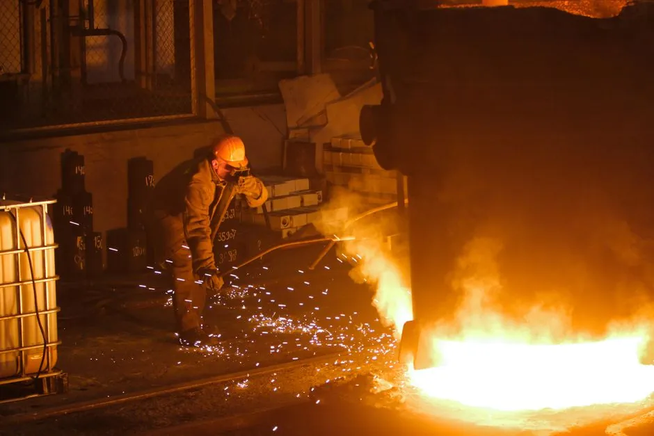
Thermocouple selection is a constraint-satisfaction problem, not a brand decision: pick the calibration letter first against temperature, atmosphere, and accuracy, then size the sheath, junction, and lead wire to the mechanical and electrical environment.
For a working engineer this means five hard gates in a fixed order, temperature envelope, chemical atmosphere, response time, sheath alloy, and accuracy class under IEC 60584 or ISA MC 96.1, before any consideration of manufacturer, head transmitter, or price. The same disciplined pass is what underpins any wider plant spec, including a temperature transmitter selection map and the cross-checks used in a heat-exchanger outlet temperature recorder spec map.
Step 1: lock the temperature envelope to the calibration letter
Each ISA/IEC letter carries a published temperature range, a tolerance band, and an EMF-vs-temperature polynomial. For oxidizing service, Type K (NiCr/NiAl) covers approximately 0 to 1260 C and is the workhorse for furnaces, kilns, and turbine inlets up to about 1100 C; its standard tolerance is plus or minus 2.2 C or plus or minus 0.75 percent of reading, whichever is greater [S1]. Type J (Fe/Constantan) spans 0 to 760 C, is restricted to reducing or vacuum atmospheres, and is widely used in plastic processing where the 0 to 400 C window dominates.
Type S (Pt-10 percent Rh/Pt) is the noble-metal reference for 0 to 1480 C, with standard tolerance near plus or minus 1.0 C or plus or minus 0.25 percent of reading above 600 C, and is specified for heat-treatment furnaces, primary calibration baths, and emissions monitoring above 1100 C. Type T (Cu/Constantan) is unique in retaining accuracy down to approximately minus 200 C, which makes it the default for cryogenic lines and HVAC refrigerant monitoring where RTDs become impractical.
Step 2: match atmosphere, then sheath alloy
Atmosphere is the silent killer of thermocouples. Type J iron leg oxidizes rapidly above 540 C in oxidizing service, so it must not be specified for open-air furnace work. Type K suffers from "green rot," a chromium oxidation that drives the negative leg negative and creates drift in the 800 to 1050 C window in reducing atmospheres with trace sulphur [S2]. Type S and Type R resist oxidation but are poisoned by reducing atmospheres, metallic vapours, and phosphorous, which calls for a sealed alumina sheath plus a gas purge in any heat-treat cell that handles bright annealing.
Sheath material follows the same logic. 304 stainless is acceptable to about 900 C in clean air; 316 stainless extends to about 925 C with better chloride resistance; Inconel 600 is the default for Type K up to 1150 C; for Type S service beyond 1100 C in combustion gases, a recrystallized alumina (Al2O3) sheath or a silicon-carbide outer sheath with an inner alumina liner is the proven pairing. Where acids or salt spray are present, specify 316L or Hastelloy C276 for the sheath and isolate the sheath from the process by a thermowell rated to ASME B31.1 or B31.3 for the design pressure.
Step 3: response time, junction style, and probe geometry
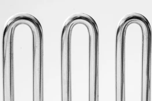
Time constant is driven by junction style, sheath OD, and tip construction. An exposed-junction Type K with 0.5 mm sheath can reach a 0.63 rise in under 0.3 s in still air, the right pick for bearing-temperature monitoring on a crusher where fast trip protection is needed. A grounded-junction probe with 6 mm sheath is closer to 4 to 6 s, suitable for most process-line temperature control. An ungrounded (isolated) junction adds another 0.5 to 1 s and is required when the sheath is electrically bonded to a pressure sensor selection line that shares a 4-20 mA loop return to avoid ground-loop noise. [S2]
Probe length is governed by immersion depth: the 3:1 rule (immersion depth greater than 10 times the sheath OD) keeps axial conduction error below 0.5 percent of reading; on a 6 mm probe that is a minimum 60 mm of tip engagement into the flowing stream, plus a thermowell tip that extends at least 50 mm past the pipe wall. For surface temperature on a motor housing, a pad-style probe with a grounded junction and thermally conductive paste is more honest than a fine-wire exposed junction, which reads only the contact patch.
Step 4: accuracy class, lead wire, and cold-junction compensation
Standard-grade (Class 2) Type K typically meets plus or minus 2.2 C or 0.75 percent above 0 C, while premium-grade (Class 1) is plus or minus 1.5 C or 0.4 percent, useful for custody-transfer steam meters and laboratory reactors. For a Class 1 S-type on a heat-treat furnace, expect plus or minus 1.0 C or 0.25 percent above 600 C, but only if the cold junction is held within plus or minus 1 C and the lead wire is the correct ISA extension grade: KX, JX, SX/RX, or TX, with no copper-only run in the field. [S1]
Cold-junction compensation belongs at the transmitter, not at the junction box, because the box can sit on a hot pipe rack. A modern head-mounted temperature transmitter with IEC 60584 linearization corrects both the EMF polynomial and the CJC sensor in the same ASIC; older 4-wire RTD-based CJC bricks drift if the box is exposed to direct sunlight. Use shielded, twisted extension cable with the shield grounded at one end only, and keep thermocouple conductors physically separated from parallel 480 V runs, where 50/60 Hz pickup can show up as 1 to 3 C of jitter on a sensitive millivolt input.
Step 5: decision matrix, who should pick what
For a typical 0 to 1100 C oxidizing furnace, specify Type K, Inconel 600 sheath, ungrounded junction, 6 mm OD, Class 1 tolerance, and a KX extension to a head-mounted transmitter; this covers the majority of chemical, petrochemical, and metals duty. For 0 to 1500 C clean combustion or heat treatment, Type S with alumina sheath and Class 1 tolerance is the only defensible choice; budget 5 to 10 times the cost of Type K and accept the 0 to 50 C warm-up drift on the first cycle. [S1]
Avoid Type J on any open-air or oxidizing service above 540 C: the iron leg oxidizes, drift accelerates, and replacement intervals drop to weeks. Avoid bare Type K in reducing sulphur-bearing flue gas without a gas-tight protective sheath: green-rot failure within a quarter is common and a documented field failure mode. For cryogenic service below minus 80 C, do not choose Pt-100 RTDs when a Type T thermocouple gives equivalent accuracy at lower installed cost and faster response.
Failure modes, traceability, and field signals
The three most common field failures are open circuit at the head, drift from atmosphere attack, and CJC errors from a sun-heated terminal block. An open thermocouple reads upscale on most instruments because the high-impedance input is pulled to the positive rail; a sustained over-range reading at the DCS with the furnace known to be cold is the textbook signature. A drifting reading in a reducing atmosphere, especially a Type K reading low by 10 to 30 C after a few weeks at 900 C, points to green rot and a sheath or atmosphere audit. A reading that swings 2 to 5 C with daytime sun on the head points to a CJC problem; shading the head or relocating the CJC sensor to the transmitter fixes it. [S2]
Trackable signals for the next spec pass: confirm the latest revisions of IEC 60584-1 (thermocouple tables) and IEC 60584-3 (extension and compensating cables) before release, require a calibration certificate traceable to NIST or NPL for any Class 1 S-type on a primary heat-treat furnace, and pin the sheath OD, immersion length, and thermowell material to the MRO spares list so that the field-replaced probe matches the original specification. Pairing this discipline with a pressure gauge spec-first pass keeps the whole instrument loop consistent on a single work-package.
Spec-level background on the components involved: pressure transmitter, and flow meter.