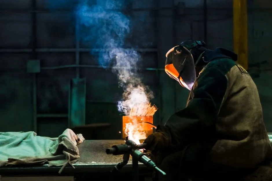
A standard TIG torch integrates the welding current conductor and the argon shielding-gas line inside a single combined cable, with the power terminated in a 35-50 mm Dinse-style twist-lock connector at the machine end [S1][S4].
The two-fluid-in-one-jacket design is the dominant configuration on WP-9, WP-17, WP-18, WP-20, and WP-26 series torches, whether air-cooled or water-cooled [S2][S4]. For background on the welding process itself, see the TIG welder reference.
Combined cable architecture: gas inside, conductor outside
On an air-cooled TIG torch, the shielding gas and the welding current travel in the same cable assembly, with the gas line inside and the copper power braid or conductor wrapped on the outside, behaving similarly to a SY-type shielded cable [S2]. Forum technicians describe the construction explicitly: the cable up to the torch has a gas tube on the inside and the power up the outside [S2].
Because the same gas stream both cools the current-carrying conductor and feeds shielding gas to the tungsten nozzle, the gas flow doubles as the cable's cooling medium on air-cooled rigs [S4]. This dual role is what lets a single 3.8 m (12.5 ft) to 7.6 m (25 ft) hose carry both services without a separate coolant loop, and it is why a replacement cable must always be specified as gas-pass-through rather than as a bare power lead [S1][S3][S4].
Connector types and machine-end terminations
The machine end of a TIG torch almost always uses a 2-pin Dinse-style power connector (commonly 35 mm² for 200 A air-cooled torches and 50 mm² for higher-amperage water-cooled torches) plus a separate barbed or threaded gas inlet fitting that mates to the welder's argon outlet [S1][S3]. Catalog offerings explicitly distinguish a "TIG Power Adapter" series, such as the 35 Gas-Cooled Gas-Thru TIG Cable Connector for 26-series torches [S1].
Connector naming follows the torch series: a WP-17 torch uses a 17-series cable and connector, a WP-26 uses a 26-series cable, and so on, with series numbers tied to rated current (17 at roughly 150 A air-cooled, 26 at roughly 200 A air-cooled) [S4]. Cross-wiring a 17-style connector onto a 26-style torch body is a common cause of overheating at the Dinse joint because the contact cross-section is undersized for the current class [S4].
Air-cooled vs water-cooled plumbing at the torch end
On a typical water-cooled torch, the machine end carries three hose fittings instead of two: a right-hand 5/8-18 UNF gas feed that supplies shielding gas into the torch head, a left-hand 5/8-18 UNF water-in feed from the cooler, and a left-hand 7/8-14 UNF water-return line that screws into a manifold before returning warm water from the power cable [S4]. Using left-hand threads on water fittings is intentional, so the water hoses cannot be cross-mated to the shielding-gas port at the cooler manifold [S4].
On air-cooled torches, the same right-hand-thread gas fitting at the machine end is the only fluid port; the gas is then routed internally down the cable to the torch head, and the cable jacket and conductor rely on the gas stream plus ambient air for cooling [S2][S4]. A practical rule from technicians: a 17-style air-cooled torch is rated to about 150 A, while a 26-style air-cooled torch is rated to about 200 A, and exceeding those values without water cooling causes rapid jacket and connector damage [S4]. For related cabling infrastructure on the welder primary side, see the power cable reference.
Common connection errors and how to avoid them
The most frequent mistake is buying a power-only cable or a non-gas-pass-through assembly and then trying to feed argon through the same jacket, which either leaks at the Dinse boot or starves the tungsten of shielding gas [S1][S3]. Catalog SKUs explicitly advertise "Gas-Thru" or "Gas-Cooled" in the product name to flag pass-through capability, and buyers should reject any replacement cable whose listing does not confirm the gas hose [S1][S3].
The second most common error is mating a gas hose to the wrong threaded port on a water-cooled manifold. Because water-in and water-return both use left-hand 5/8-18 threads, they are physically interchangeable with each other but not with the right-hand gas fitting; cross-threading or forcing a left-hand water fitting into a right-hand gas port will strip the manifold [S4]. A reliable field check is to confirm thread handedness and to pressurize the gas line alone at about 0.5-1.0 bar (7-15 psi) before powering the torch, listening for leaks at every fitting [S4].
Selection criteria and a side-by-side comparison
Selecting a TIG torch cable boils down to four decision criteria: torch series (17/18/20/26), cooling class (air vs water), current rating, and physical length. Matching all four against the welder's Dinse and gas outlet geometry is the only way to guarantee a clean hookup [S1][S3][S4].
The table below lines the main cable configurations against the four criteria so procurement and shop-floor staff can compare options directly. Comparison data is drawn from the connector catalog and forum field reports, not from any single OEM manual [S1][S3][S4].
WP-17 air-cooled combined cable: 17-series torch, air-cooled, rated to about 150 A DC, typical lengths 3.8 m and 7.6 m (12.5 ft and 25 ft), 35 mm² Dinse, single right-hand gas fitting at the welder [S4].
WP-26 air-cooled combined cable: 26-series torch, air-cooled, rated to about 200 A DC, typical lengths 3.8 m and 7.6 m, 35 mm² or 50 mm² Dinse depending on catalog, single right-hand gas fitting at the welder [S1][S4].
WP-20 water-cooled combined cable: 20-series torch, water-cooled, rated above 200 A DC, 50 mm² Dinse, three fittings at the welder (RH 5/8-18 gas, LH 5/8-18 water-in, LH 7/8-14 water-return to manifold) [S4].
WP-9 / WP-18 micro-TIG combined cable: 9 or 18-series torch, air-cooled, low-amperage (typically under 100 A) fine work, smaller-gauge Dinse or threaded stud, single right-hand gas fitting at the welder [S2][S3].
What to verify before first power-up
Before striking an arc, three checks cover most field failures. First, confirm the Dinse connector is fully inserted and twisted until the contact shoulder seats, because a partially seated 35 mm² connector on a 200 A torch will heat within seconds and anneal the contact [S1][S4]. Second, leak-test the gas circuit with shop air or argon at 0.5-1.0 bar (7-15 psi) and a drop of soapy water at every fitting, listening for the telltale hiss that points to a loose hose clamp or a cracked jacket at the torch-end grommet [S4].
Third, on water-cooled torches, run the cooler for 30-60 s with the return line disconnected and verify clean, bubble-free flow, then reconnect; any milky water or air gap indicates a failing pump or a leak that will cook the power cable if left in service [S4]. A useful adjacent reference for plumbing and pressure checks on the gas side is the checking and testing apparatus entry, which covers the gauge and regulator hardware that sits upstream of this hose. For a wider view of the cabling and connector ecosystem used around welding workstations, the welding and cutting tool reference collects the related consumable and accessory categories.
Trackable signals for the next buying cycle: (1) whether your supplier stocks "Gas-Thru" or "Gas-Cooled" replacement cables in the exact WP-series you run, since generic 35 mm² power-only cable is widely available but pass-through cable is not [S1][S3]; (2) whether the cooler-side manifold on a water-cooled rig uses 5/8-18 LH and 7/8-14 LH fittings, because some European machines use metric equivalents that require an adapter [S4].
Background reading: Fixed gas detector HART diagnostics over the 4-20 mA loop: wiring, signal, and selection.