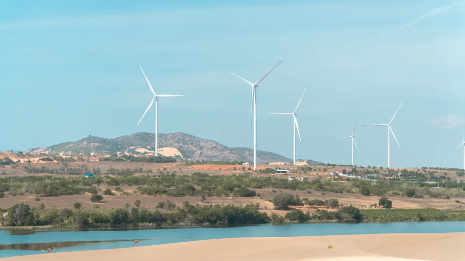
For utility-scale wind turbines, the engineering-relevant timing belt choice is a curvilinear HTD or GT2/GT3 profile in 8M (8 mm) or 14M pitch, with the design power calculated as Pd = Pt × Ks and the overload coefficient assembled from load, idler, speed-ratio, and operation-time sub-factors per the standard timing-belt sizing procedure [S1][S3].
Wind turbines do not use a single belt type across the whole machine: yaw, pitch, gearbox, and generator-side auxiliaries each carry different torques, speeds, and service factors, so the belt family is typically chosen per subsystem rather than per turbine [S2].
Where Timing Belts Actually Sit Inside a Wind Turbine
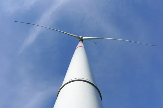
Synchronous and V-belt drives in renewable energy plants are used to transmit rotational energy between the turbine blades, gearboxes, and generators, and to drive yaw rotation, blade pitch adjustment, cooling fans, and lubrication pumps [S2]. Inside a wind turbine specifically, belts appear in three distinct subsystems: the main gearbox/generator coupling (often a multi-rib or V-belt arrangement on smaller machines, synchronous on larger gearboxes), the yaw drive that rotates the nacelle to face the wind, and the pitch drive that adjusts each blade's angle of attack [S2].
Each subsystem has its own duty cycle. The yaw drive runs intermittently, at low speed, with high holding torque when parked; the pitch drive sees high cycle counts per hour and must hold blade position under aerodynamic load; auxiliary drives for cooling and lubrication fans run near-continuously at moderate load [S2]. That split is the reason a single "wind-turbine timing belt" does not exist as a stock line, and why specifying by subsystem is the only reliable starting point [S2][S3].
Curvilinear HTD/GT vs Trapezoidal: Why Pitch Class Matters
Curvilinear tooth profiles (HTD and Gates GT2/GT3) deliver roughly 20–40% higher torque capacity than trapezoidal profiles at the same pitch and belt width, with lower noise and longer fatigue life because contact stress is distributed across the rounded tooth face instead of concentrating at the root [S4].
Trapezoidal profiles (MXL, XL, L, H, XH, XXH in imperial; T2.5, T5, T10, AT5, AT10 in metric) remain in service where legacy interchangeability is mandatory, but for new wind-turbine designs the current engineering standard is curvilinear, with 8M and 14M pitch covering the medium and heavy duty bands and 5M pitch covering smaller auxiliary drives [S3][S4]. For a related read on tooth geometry and how it interacts with pulley face width, see the timing belt pulley selection guide and the timing pulley reference page.
Design Power Calculation: Pd = Pt × Ks
The Misumi timing-belt sizing procedure defines design power as the transmission power (typically the motor's rated output, or ideally the actual load on the belt) multiplied by an overload coefficient Ks, which is itself a sum of correction sub-factors: load (Ko), idler (Ki), speed ratio (Kr), operation time (Kh), and for servo drives a start/stop factor (Km) [S1].
The load correction factor Ko varies from 1.0 for exhibit and medical instruments on intermittent duty to 2.1 for reciprocating compressors, conveyors handling ore or coal, and rotary compressors under continuous duty with high peak loads, so the same physical prime mover can demand very different belt sizes depending on what it is driving [S1]. Wind-turbine pitch and yaw drives sit in the high end of that table because the load is dominated by aerodynamic holding torque with significant peak events, and a designer who skips the Ko–Kh split usually under-specifies the belt by one or two pitch sizes [S1][S3].
Tooth Shear vs Belt Break Strength
A single timing-belt tooth carries only a fraction of the belt's full break strength, which is why timing-belt selection procedures check tooth shear capacity against the design power rather than relying on the belt's published tensile rating alone [S5].
For wind applications this matters at the pitch drive, where the belt is short, the pulleys are small relative to the torque, and individual tooth engagement is the limiting factor rather than the belt's overall strength. Practical consequences: wider belts (within the same pitch) distribute load across more teeth in mesh, so going from a 20 mm wide 8M belt to a 50 mm 8M belt at the same torque roughly multiplies tooth-share capacity proportionally; this is also why pulley face width is specified as belt width plus 1–2 mm clearance per side rather than flush to the belt [S4]. For complementary background, the timing belt encyclopedia entry covers tooth-share geometry in more detail.
Five-Variable Selection Checklist for Wind Service

Texas Belting's selection guide lists the five variables a designer has to lock down before picking a part number: tooth profile, pitch, belt width, belt length, and belt material, and warns that getting any one wrong risks premature failure or equipment damage [S3].
Applied to a wind-turbine pitch drive, that translates to: curvilinear profile (HTD or GT2), 8M or 14M pitch sized to the design power from the Pd = Pt × Ks calculation, belt width chosen so tooth-share stress stays below the manufacturer's limit, belt length set by the yaw-or-pact axis centre distance and any tensioner travel, and belt material (typically chloroprene rubber with fiberglass or aramid tensile cords, or polyurethane with steel cords for higher precision) selected for the operating temperature window at the nacelle, which can swing from -30°C in winter start-up to +70°C in summer continuous operation [S3][S5]. The belt tensioner reference page covers how idler placement changes the effective Ki factor in the design-power equation [S1].
Comparison: Trapezoidal vs Curvilinear for Wind Subsystems
Two profile families dominate the decision matrix for wind service. Trapezoidal (MXL, XL, L, H) gives legacy interchangeability and lower unit cost, accepts concentrated root stress, suits miniature through medium duty, and typically tops out around the L/H pitch band for new designs [S3][S4]. Curvilinear (HTD 3M/5M/8M/14M, GT2/GT3 2 mm through 14M) gives +20–40% torque capacity at equal pitch, lower noise, longer fatigue life, and is the current engineering standard for new high-torque drives including pitch and yaw service [S3][S4].
For medium-duty yaw drives at moderate speed, an 8M HTD belt is a common specification; for high-torque pitch drives on multi-MW turbines, 14M HTD or 14M GT2 is more typical; and for small auxiliary drives (cooling fans, lubrication pumps) a 5M HTD or even T10 trapezoidal is often sufficient [S3]. This is a criteria-based split, not a brand split, and it is the same logic Mitsuboshi and SDP-SI apply in their renewable-energy and timing-belt handbooks [S2][S5].
Standards, Sourcing, and Failure Modes to Track
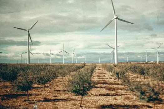
Wind-turbine belt service is governed less by a single named standard and more by manufacturer design procedures (Gates, Mitsuboshi, Continental, Bando, Megadyne) cross-referenced against the turbine OEM's gearbox and pitch-system specs, plus general machine-design standards for shaft and bearing sizing on the driven side [S1][S2][S3][S5].
The most common failure modes in wind service are tooth shear from under-specified design power (skipping the Ks sub-factor sum), tooth jump from shock load on the pitch drive during emergency feather, side travel from misalignment between pulley flanges, and cord fatigue from operating outside the temperature window of chloroprene or polyurethane compounds [S1][S5]. The Mitsuboshi renewable-energy line explicitly targets reduced downtime and reliable clean-energy output as the design drivers, which is consistent with how wind OEMs frame the spec: minimise scheduled maintenance climbs, because tower climbs are the dominant lifetime cost on a utility-scale turbine [S2].
Trackable signals over the next reporting period: any new IEC or AGMA maintenance standard that pins timing-belt service intervals on wind turbines to a specific cycle count rather than calendar time, and any published field-data set correlating HTD vs GT2 fatigue life in pitch-drive service at the 14M pitch band. For a related decision-matrix article on a different but adjacent industrial selection problem, see the band saw blade TPI selection for aluminium risers and gates write-up.