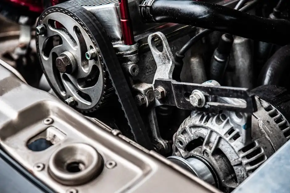
PLD (Pitch Line Differential) is the radial distance from a timing belt's tensile cord to the bottom of its tooth root, and applying the wrong U value to the formula OD = PD − 2U is the most common reason a calipered pulley disagrees with a catalog OD chart [S1].
The correction is profile-specific, not universal: each belt family from XL and L in inch pitches to HTD 3M/5M/8M and GT2/3/5 in metric curvilinear profiles publishes its own U constant, and that constant is what an engineer must look up before subtracting 2U from the calculated pitch diameter [S1][S2]. A 20-tooth HTD 5 mm pulley, for example, has PD = (5 × 20) / π = 31.83 mm; with the published U of 1.49 mm, the OD lands at 28.85 mm, a value that matches stock supplier tables for that exact tooth count [S1].
Why PLD Changes With Profile, Not With Tooth Count
PLD equals the height of the belt tooth above the neutral axis, so it is a property of the belt's pitch family, not of the pulley that carries it [S1]. The pitch line itself is the constant-length neutral axis running through the belt body, and the tensile cord sits on that line; everything above the line is tooth, and that tooth height is what gets subtracted twice (once on each side of the diameter) when converting PD to OD [S1].
Because the cord is below the tooth tip, the OD you can measure with a micrometer is always smaller than the imaginary PD circle, a relationship repeated across every standard pitch profile from XL through GT [S1]. Reading the wrong U for the wrong family is the practical failure mode: a pulley ordered as HTD 5 mm will not give the same OD as the same tooth count in XL at 5.08 mm even though both are roughly "5 mm pitch" [S1]. Pfeifer, SDP-SI, and ContiTech each publish these U values in their pitch tables rather than encoding them in the pulley part number, so the design step is always a table lookup against the chosen belt family [S1].
PD and OD Across Common Tooth Counts
Pitch diameter is a pure geometric construct, computed as PD = (p × N) / π, with p the belt's tip-to-tip tooth spacing and N the number of pulley teeth [S1][S2]. The pitch is constant for any given belt family, so PD scales linearly with tooth count, which is why catalog tables typically publish a per-tooth PD coefficient and let the engineer multiply by N [S2].
Worked values for a 20-tooth pulley across common profiles illustrate how pitch dominates diameter: GT2 (2 mm pitch) gives PD ≈ 12.73 mm, GT3 (3 mm) gives 19.10 mm, GT5 (5 mm) gives 31.83 mm, and MXL (2.032 mm / 0.080 in) gives 12.93 mm [S2]. At 24 teeth, HTD 3M sits at 22.92 mm PD and HTD 5M at 38.20 mm, while HTD 8M with 30 teeth reaches 76.39 mm PD, the kind of large-pitch power-transmission size where the 1–3 mm PLD offset becomes a small but non-trivial fraction of the total diameter [S2]. The timing pulley reference page carries the same per-profile grid for designers who want a single lookup table at the bench.
Profile-by-Profile U Values and Their Effect on OD
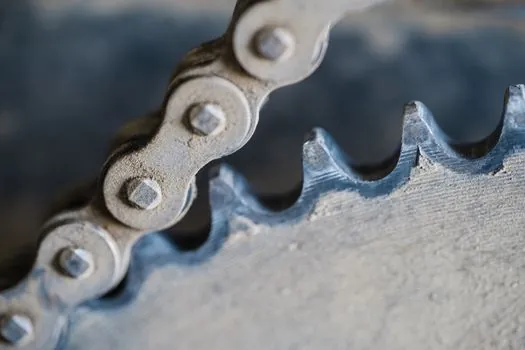
The trapezoidal XL and L imperial profiles use small U values because the tooth depth is shallow relative to the pitch: a 36-tooth XL pulley at 0.200 in (5.08 mm) pitch computes to PD = 2.292 in, and subtracting 2U with the published XL U lands the OD in the 2.13 in range that matches SDP-SI's table [S1]. The L profile at 0.375 in pitch with 24 teeth yields PD = 2.864 in, a diameter where the same U correction still removes only a fraction of a millimetre per side because the tooth is proportionally short [S1].
HTD 5M is the canonical worked example: PD for 20 teeth is 31.83 mm, U is 1.49 mm, so 2U = 2.98 mm and OD = 28.85 mm, exactly the figure Illinois Pulley & Gear's table lists for that tooth count [S1]. GT2 and GT3 use smaller U values again because the curvilinear GT tooth is shallower than the HTD tooth, and a 20-tooth GT2 pulley therefore has an OD only about 1.2–1.4 mm below its PD rather than the ~3 mm gap seen on HTD 5M [S2]. Free online generators such as the GearForge GT2/HTD/T5 tool and the Meiya Precision calculator let engineers type in Z and p and read back PD, OD, and belt length in one pass, useful when the U for a less common family (P3M, S8M, AT10) is not committed to memory [S4][S5].
Criteria Comparison: U Offset by Belt Family
The table below lines up the most common profiles against three decision criteria designers weigh when picking a belt family for a new synchronous drive. U values are quoted as published in the standard pitch tables referenced in the source material; where a profile's U is profile-only and does not scale with tooth count, the table reflects that [S1][S2].
XL (5.08 mm pitch, imperial trapezoidal) carries a small U around 0.51 mm (0.020 in), so 2U removes about 1.0 mm from PD; the family is cheap and stock-deep but limited to light-load office and 3D-printer service. L (9.525 mm / 0.375 in) doubles the pitch and roughly doubles the U, so 2U is around 2.0 mm and OD tracking against PD is still close. HTD 5M with U = 1.49 mm is the workhorse for mid-power automation, while HTD 8M triples the U again because the curvilinear 8 mm tooth is much taller, making the OD gap the largest fraction of any small-pitch GT/HTD pulley. GT2 (2 mm) and GT3 (3 mm) keep U small (around 0.6–0.8 mm and 0.9–1.1 mm respectively) so backlash-sensitive positioning stages see minimal OD-to-PD mismatch. T2.5/T5/T10 trapezoidal metric profiles sit between XL and HTD 5M in U magnitude, which is why the same Z count across T and HTD does not give the same OD [S1][S2].
When Standard U Values Break Down: Small Tooth Counts and Stock Tolerances
Below roughly 14 teeth on a metric pitch or 16 teeth on an imperial pitch, the standard U value still applies in theory, but the small PD amplifies the percentage error from any tooth-profile manufacturing tolerance, and slip or ratcheting risk rises for any drive that needs positive torque transfer [S2]. A 12-tooth drive into a 48-tooth load is still a 4:1 reduction with exact ratio from tooth counts, but the engineer should add a small PLD tolerance (typically ±0.05 mm on GT2, ±0.1 mm on HTD 5M) to the OD dimension when the drive is going into a tight enclosure or a custom belt-tensioner bore [S2].
For V-belt and flat-belt sheaves, the same PD/OD distinction applies but there are no teeth to count, so the ratio is taken directly from the sheave's published pitch diameter and there is no PLD correction to apply [S2]. This is also why mixing OD and PD in a multi-stage drivetrain is the most common sizing error in flat-belt systems: PD is where the belt's tension line actually sits, not the rim you can measure [S2]. The reference on timing belt profiles carries the cross-profile tooth-depth data for engineers building such mixed drives.
Standards, Sourcing, and Cross-Reference Discipline
Published PLD values come from the belt manufacturers themselves (Pfeifer, SDP-SI, ContiTech, Gates) and from authoritative distributors such as Illinois Pulley & Gear, not from a single ISO or AGMA standard for the U constant [S1]. Engineers who need an audit trail should cite the specific catalog and revision when the U value is on a print, because the same profile family can carry slightly different U values between manufacturers for the same nominal pitch.
For sourcing, a 20-tooth HTD 5M pulley is a stock item across most industrial suppliers and the OD = 28.85 mm figure can be cross-checked directly; less common profiles (P3M, S8M, AT10) are typically custom-cut or made-to-order, and the PLD offset must be requested from the belt maker rather than inferred from a generic table [S1][S4]. The GearForge timing-belt pulley generator exports STEP and STL files for laser-cut or 3D-printed prototypes, and the Meiya Precision calculator covers 30+ profiles from MXL through AT20, which is enough breadth to handle most FRC, CNC, and small-automation designs that come across a motion engineer's desk in 2026 [S4][S5].
Track the next PLD-related decision point on October 13, 2026, when Gates is expected to refresh its 2026 power-transmission catalog with revised HTD 8M and GT3 U values; engineers specifying 8M-pitch drives above 30 teeth should re-cross-check OD against the new tables before locking the print.
Component reference pages worth checking: reactive power compensation.
Background reading: Selective vs Drive-In Pallet Rack: Density, Access, and Cost Trade-Offs.