
Electronics tooling spans three distinct wear regimes: plastic-injection cavities, PCB and connector stamping dies, and aluminum or zinc die-cast inserts, and each regime now has a default AISI/SAE grade backed by published composition and hardness data [S1][S2].
The decision pivots on five variables: dimensional tolerance (often ±0.01 mm for connector molds), surface finish, expected cycle count, thermal exposure, and whether post-machining heat treatment is allowed, with the wrong choice driving 200-300% swings in tool life on long runs [S1]. For background on how these steels are used in tool and die steel cavity and cutting applications, the cold-work and hot-work splits below apply directly to electronics work.
Plastic-Injection and Connector Cavities: P20, NAK80, H13
P20 is the pre-hardened, 30-32 HRC general-purpose mold steel delivered in the machinable condition, with an annealed BHN around 100 listed in the AISI comparison table, so it can be EDM'd or milled to tolerance without quench-cracking risk on molds over 1 ton [S1][S2]. NAK80 is the age-hardening upgrade for ±0.01 mm tolerance work in electronics: uniform precipitation hardening means the cavity moves less than a quench-hardened grade, which is why high-precision connector and leadframe molds default to it [S1]. H13 (5% Cr, air-hardening) enters the picture for high-temperature molding or any insert adjacent to a hot runner, and remains the standard hot-work die steel for the linked die casting die applications on the same floor [S2].
Selection gate: if the part is a cosmetic enclosure under 500,000 shots, P20 is the cost-correct answer; if the tolerance is below ±0.02 mm or the cavity is polished to SPI-A2, step up to NAK80; if melt or hot-runner temperature exceeds 300°C continuously, switch to H13 even at higher unit cost [S1][S6].
Stamping, Blanking, and PCB Punching: A2, D2, M2
A2 tool steel (5% Cr, air-hardening) carries 0.90-1.05% C, 4.90-5.30% Cr, 0.90-1.10% Mo, and 0.15-0.20% V, hardens to 57-62 HRC from a 1700-1800°F austenitize, and is recommended over O1 whenever heat-treatment distortion must stay inside tight punch-to-die clearances [S3]. D2 (1.50-1.60% C, 11.50-12.00% Cr, 0.80-1.00% V) hits 54-61 HRC and is the go-to for high-wear blanking, lamination, and glass-filled-PCB punching, where 12% chromium is enough to suppress adhesive wear without crossing into stainless territory [S3]. M2 (the high-speed tool steel) is reserved for cutting and piercing applications where the punch tip runs above 600°C from adiabatic shear, and is rarely needed in electronics stamping [S2][S6].
Annealed-BHN reference for the comparison set: A2 sits at 248, D2 at 255, both cold-drawn up to 269 BHN, and the tempering curves show A2 holding 56-58 HRC at 800°F versus D2 at 57-59 HRC at 700°F, which is why D2 wins for long abrasive runs and A2 wins when some impact toughness is needed [S2][S3].
Hot-Work and Die-Cast Inserts: H13, S7, H11
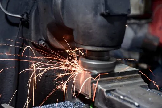
H13 (0.32-0.45% C, ~5% Cr, 1.0-1.5% Mo, 0.8-1.2% V) is rated for service above 400°C and is "especially suitable as a die steel for aluminum and magnesium die casting," which makes it the default insert and shot-sleeve-adjacent material for electronics housings cast in Al or Mg alloys [S2][S6]. S7 (0.45-0.55% C, 3.0-3.5% Cr, 1.30-1.80% Mo) is the shock-resistant alternative for hot-work tools that take sudden impact loads, with a 1000°F service ceiling and good ductility for cold and medium hot work [S2].
Selection gate: aluminum and magnesium die-cast tooling for die casting die cores is H13 by default; if the tool sees press-side impact rather than steady thermal cycling, swap to S7; if the cavity is also subject to mild corrosion from coolant, evaluate 420ESR as a stainless mold-steel alternative [S2].
Impact, Wear, and Red-Hardness Trade-off
Tool steel selection lives on a three-axis "Performance Iron Triangle" of wear resistance, toughness, and red hardness, and the alloying system is what shifts a grade between them: carbon drives hardness, chromium drives wear and corrosion resistance (passive film forms around 12% Cr), molybdenum drives toughness and hardenability, and vanadium drives wear resistance through hard VC carbides [S1][S5]. D2 and the A-series sit on the high-wear vertex, S7 and the S-series on the high-toughness vertex, and H13, M2, and T1 on the high-temperature vertex [S6][S7].
Decision matrix for an electronics tool designer: if the failure mode is abrasion, choose a D-series or PM grade; if it is chipping or cracking, drop to an S-series or A-series; if it is heat-checking or thermal fatigue, move to H13 or an H-series hot-work grade; and if none of the three dominate, an O1 or A2 mid-range grade is the safe call [S6].
Heat Treatment, Tempering, and Dimensional Control
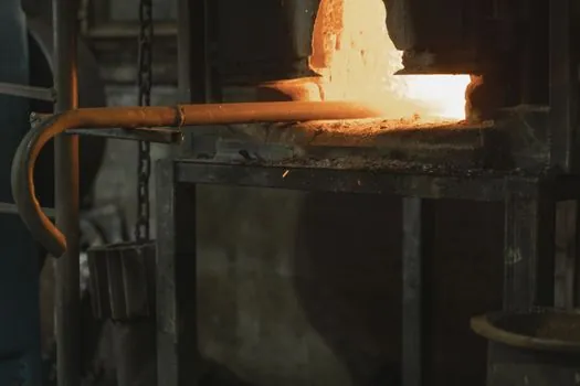
A2 hardens from 1700-1800°F and tempers in the 350-1000°F band to land at 60-62 HRC after a 400°F temper, dropping to 54-56 HRC after a 1000°F temper, so the post-temper heat age of the cavity is a real tolerance variable for precision connector molds [S3]. D2 uses a higher 1800-1875°F austenitize and a 400-1000°F temper band reaching 58-60 HRC at 500°F, which is the standard "high wear, moderate toughness" profile for long-run blanking [S3]. O1 oil-hardening data shows 64-66 HRC as-quenched, sliding to 60-61 HRC at 400°F, 57-58 HRC at 600°F, and 46-48 HRC at 800°F, a far steeper hardness-vs-temperature curve than A2 [S4].
Practical rule: specify the as-tempered hardness window on the print, not just the grade, and use age-hardening NAK80 or pre-hardened P20 whenever a downstream heat-treat step would move the cavity off ±0.01 mm tolerance [S1].
Comparative Grade Snapshot for Electronics Tooling
The table below lines up the main candidate grades against four decision criteria for electronics work; raw data points are pulled from the AISI and supplier data sheets cited above. [S1]
Plastic-injection cavity, ≤500k shots, ±0.05 mm tolerance: P20, 30-32 HRC pre-hard, low distortion, lowest cost, poor for high polish or high temp [S1][S2].
Connector or leadframe cavity, ±0.01 mm, SPI-A1/A2 polish, 1M+ shots: NAK80, age-hardened to ~40 HRC, uniform hardness, premium cost, no post-machining heat treat [S1].
Stamping / blanking / PCB punching, abrasive wear-dominant, 54-62 HRC: D2, 12% Cr, deep-hardening, slow to grind, best for long abrasive runs [S2][S3].
Stamping with impact, mid-wear, safer hardening: A2, 5% Cr, 57-62 HRC, lower distortion than O1, balanced all-rounder [S3].
Aluminum or magnesium die-cast insert, ≥400°C service, thermal-fatigue-driven: H13, 5% Cr hot-work, red-hard, the default for Al/Mg die casting [S2][S6].
Hot-work impact tooling, shock loads dominant: S7, 1000°F ceiling, high ductility, replaces H13 when failure mode is chipping rather than heat-checking [S2].
Limits, Failure Modes, and When Not to Pick a Tool Steel
Tool steels fail in three recurring ways: gross fracture (toughness too low, choose S-series), wear/abrasion (hardness or Cr-VC volume too low, choose D-series or PM), and heat-checking or plastic deformation (red hardness too low, choose H-series) [S1][S6]. D2 and the high-Cr D-family are explicitly called out as brittle grades to avoid in shock-loaded applications, and substituting D2 for S7 in a punch-and-die set subject to misfeed impact is a common specification error [S6].
Stainless mold steels (e.g., 420ESR, S136/P20+S-stainless variants) only earn their premium when the cavity sees a corrosive polymer, a wet molding environment, or medical-grade cleaning chemistry; for dry-run general-purpose electronics plastic molds, the corrosion resistance is wasted budget [S2][S5]. For plastic-injection work paired with die casting machine cells, never use the same H13 for both shot-sleeve and cavity insert without confirming the nitriding or coating spec, because shot-sleeve wear is a different tribology than cavity wear [S2].
Selection Workflow and Sourcing
Step 1, lock the part-side requirements: tolerance band, surface finish, shot count, melt or process temperature, and any corrosive exposure. Step 2, lock the heat-treatment window the shop can actually run, because a grade that needs a vacuum furnace is wasted on a shop with only atmospheric furnaces. Step 3, pick a grade from the AISI family that meets both; the AISI classification (W, O, A, D, S, M, H, P) and the published annealed-BHN table are the minimum documentation to attach to a tooling PO [S2][S7].
Step 4, on the print, specify composition range (e.g., 1.50-1.60% C, 11.50-12.00% Cr for D2), as-tempered hardness window, surface finish spec, and required delivery hardness (annealed vs pre-hardened) [S3]. The JEELIX case data on H13 vs P20 for high-volume molds is a useful reference point: an H13 mold carrying a 30% price premium over P20 extended life by 200-300% on a one-million-part run, halving the amortized tooling cost and cutting maintenance-related downtime by up to 40% [S1].
Trackable signals: the 2026 revisions to PM (particle-metallurgy) and high-V tool-steel catalogs (PM 10V at ~9.75% V, PM 15V at ~14.5% V) keep extending the wear envelope for PCB punching and connector stamping where conventional D2 reaches its grindability limit [S7]. On the gravity die casting machine side, gravity-cast Al electronic housings continue to skew the H13 vs S7 decision toward H13 whenever the cycle is hot and short, which is the default in current Al housing production [S2][S6].
Related analysis: Carbon Steel Selection for Rail Industry: Grades, Specs, and 2026 Buying Signals.