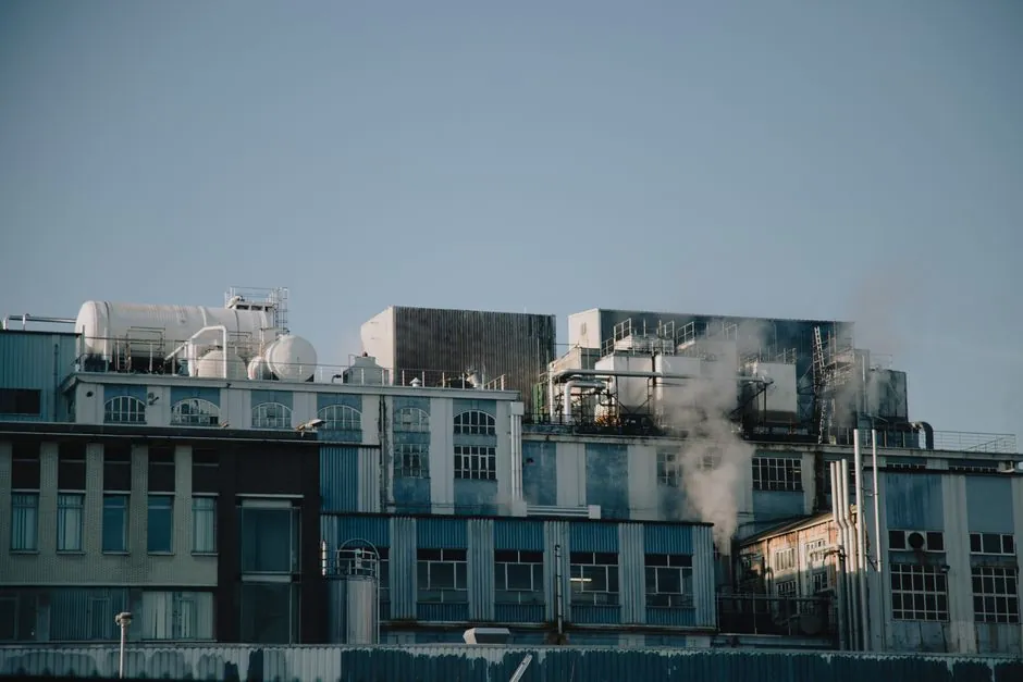
A toxic gas monitoring system (TGMS) integrates with a plant DCS through a dedicated controller that powers field detectors, conditions their analog or HART signals, and forwards alarm and concentration data over industrial protocols such as Modbus TCP, Modbus RTU, Profibus, Profinet, or HART, depending on the controller class [S4].
TGMS is a life-safety layer, classified separately from basic process control, and is normally wired into both the DCS for visualization and a Safety Instrumented System (SIS) or Emergency Shutdown Device (ESD) for automatic action, with the controller providing the bridge between field sensors and the higher-level control network [S3][S4].
Core Components and How the Signal Reaches the DCS
A typical TGMS consists of gas sensors located at the detection point or drawing a sample via an air pump, audible and visual signaling devices (beacons, horns), and a centralized PLC-based controller with an operator interface that displays system status and ties into fire alarm, gas delivery, and building automation systems [S3]. The control unit supplies power to connected detectors and transmitters, conditions the signal, displays measured gas concentrations, monitors limit values, actuates alarm devices, and can initiate risk-reduction measures, with connectivity options for communicating with other plant DCS or ESD systems if required [S4].
For dense plants, controllers such as MSA SUPREMATouch process up to 256 sensor inputs and 512 relay outputs, expose data over Modbus RTU, Modbus TCP, Profibus, and Profinet, and support redundant configurations up to SIL 3 under IEC 61508, the umbrella functional-safety standard referenced for such architectures [S4]. Smaller wall-mount units like SENTRY io handle 8 or 16 points with up to 56 relays, expose RS-485 Modbus RTU and Modbus TCP/IP over Ethernet, and use auto-recognition for MSA and General Monitors detectors through HART, reducing wiring cost at the device level [S4]. Emerson's DeltaV-integrated fire and gas system is one example of a vendor offering that consolidates detection diagnostics and safety-group status inside the DCS environment for plant-wide situational awareness [S2]. Honeywell's TGMS package for North American high-tech customers typically bundles Vertex, Midas, and SPM gas detection products under a single integrator scope [S1].
Detection Technologies and Where Each Fits
Five major sensor families cover nearly every TGMS duty: chemical tape, electrochemical cell, infrared, catalytic bead, and semiconductor [S3]. Electrochemical cells are the common choice for toxic gases like CO and SO2, while catalytic bead and infrared sensors are preferred for flammable gases such as methane and hydrogen; photoionization detectors (PIDs) handle volatile organic compounds where lower detection limits are needed [S5]. Sensor placement follows the physics of the target gas: heavier-than-air species such as propane or SO2 are detected near the floor, while lighter-than-air species such as H2 and CH4 accumulate near the ceiling of enclosed spaces [S5].
For a structured look at how the principal sensor families compare on the four criteria that drive most specifications, the table below lines up the typical use cases:
Comparison of mainstream TGMS sensor families on cost, target gases, and integration considerations: electrochemical cells suit toxic gases (CO, SO2, NH3, H2S) at moderate cost with a 1-3 year typical cell life; infrared (NDIR) sensors target hydrocarbons and CO2 with longer service intervals and low cross-sensitivity to humidity; catalytic bead sensors handle combustible gases below the lower explosive limit (LEL) at low cost but require oxygen to function; semiconductor sensors offer low cost for simple leak detection with reduced selectivity; and PIDs cover VOCs down to ppb levels at higher unit cost [S3][S5].
False-alarm suppression in electrochemical cells is dominated by cross-sensitivity to interferent gases, a behavior covered in detail in this cross-sensitivity reading guide, which explains how to read manufacturer cross-sensitivity tables and apply environmental compensators before the controller raises a Tier-1 alarm.
Power-Plant Duty and Placement Strategy
Power plants monitor a broad gas set: carbon monoxide (CO), hydrogen (H2), sulfur dioxide (SO2), ammonia (NH3) from selective catalytic reduction (SCR) systems, methane (CH4), and oxygen (O2) depletion in confined spaces [S5]. CO is a primary concern in coal-fired and gas-fired plants because incomplete combustion produces it continuously; H2 leaks in generator cooling systems can create explosive atmospheres even at small release rates; SO2 is acutely toxic at low concentrations; and oxygen monitoring matters wherever inert gases are used, since oxygen displacement can cause rapid unconsciousness without warning [S5].
Priority placement areas inside a power plant are generator halls, turbine enclosures, boiler rooms, fuel storage areas, battery rooms, and any confined spaces where ventilation is limited [S5]. A layered response structure converts sensor readings into staged actions: a first threshold typically triggers a visual or audible warning, while second or third thresholds can automatically start ventilation, shut down equipment, or isolate sections of the plant, which is what makes integrated gas detection a cornerstone of safety systems rather than just a monitoring tool [S5]. Toxic gas detector selection for power-plant service is a multi-variable problem: target gas, cross-sensitivity, response time, output protocol, and SIL target all have to align with the controller and DCS the plant already runs. In semiconductor fabs, the same controllers tie into a broader gas analyzer layer for process gas purity, with TGMS handling personnel protection and the analyzer handling product-quality excursions.
Applicable Codes, Standards, and SIL Targets
U.S. TGMS designs are governed by a stack of NFPA codes: NFPA 1 (Fire Code), NFPA 2 (Hydrogen Technologies Code), NFPA 30 (Flammable and Combustible Liquids), NFPA 45 (Laboratories Using Chemicals), NFPA 55 (Compressed Gases and Cryogenic Fluids), NFPA 70 (National Electric Code), NFPA 72 (National Fire Alarm and Signaling Code), NFPA 318 (Semiconductor Fabrication Facilities), NFPA 496 (Purged and Pressurized Enclosures), and NFPA 497 (Classification of Hazardous Locations) [S3]. The applicable International Codes also referenced in the same body of work include the International Building Code, International Fire Code, International Plumbing Code, and International Mechanical Code [S3].
For the detection function itself, IEC 60079-29-1 is the performance standard for gas detectors, and a system approved to that standard is qualified to initiate automatic safety actions for risk mitigation, not just to detect and alarm [S4]. Modern fire and gas controllers comply with relevant global safety standards and support redundant configurations up to SIL 3 per IEC 61508, the functional-safety reference standard for safety instrumented systems [S4]. For broader plant context, condition monitoring systems and vibration condition monitoring are typically designed to coexist with TGMS on the same DCS asset model, sharing alarm priority and operator HMI conventions, and power monitoring systems layer on top to flag the electrical precursor events that often precede a gas release scenario in turbine halls and battery rooms.
Service, Maintenance, and Lifecycle Planning
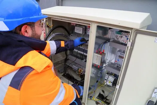
A TGMS is a life-safety system that requires a regular service and maintenance plan to maintain system integrity and ensure proper operation, with the maintenance scope defined by sensor type, duty environment, and SIL target [S3]. Modern controllers support remote one-man and group calibration through software, which reduces the labor cost of cell replacement and bump testing compared with walking every point with a calibration gas cylinder [S4]. Auto-recognition of MSA and General Monitors detectors through HART also reduces wiring expenses and configuration complexity at commissioning, and HART's ability to ride on a 4-20 mA analog loop keeps it compatible with classic DCS analog input cards while still exposing diagnostics and tag data [S4].
Where the TGMS feeds an asset-management or plant-wide reliability platform, the same controller-side diagnostic data can be shared with the concrete batching plant or process operator consoles through OPC UA gateways, allowing alarm logs to live alongside vibration and power events in a single historian view for root-cause analysis.
Selection Criteria: Who a TGMS-DCS Integration Is For, and Who It Is Not For
A TGMS tied into a plant DCS is for facilities handling highly toxic, pyrophoric, flammable, or oxygen-displacing gases, such as semiconductor fabs, nanotechnology labs, chemical plants, refineries, and power plants, where a release must trigger both an operator display and an automatic mitigation action [S3][S5]. It is not for purely environmental perimeter monitoring, where lower-cost single-point detectors without a dedicated controller or DCS interface are sufficient, and it is not a substitute for a fixed gas analyzer on a process pipe, which is a process-measurement instrument rather than a life-safety device. The bandwidth between detector and controller, and the SIL target, set the practical floor: SIL 2 is the typical minimum for personnel-protection loops, and SIL 3 is reserved for high-consequence or large-footprint installations where redundancy is required [S4].
Trackable signals for engineers watching this space over the next planning cycle: new revisions of IEC 60079-29-1 affecting detector performance approval and any expansion of SIL 3-capable controller families in the 8-16 point wall-mount class, where most North American retrofit work happens. Plant-level decision points to watch are HART-to-OPC UA gateway deployments that fold TGMS diagnostics into the same historian as vibration and power data, and the migration of legacy PLC-5-class TGMS controllers onto modern SIL 3 platforms as those legacy units reach end-of-life.