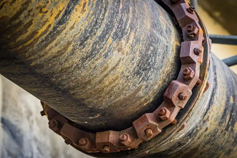
Inline ultrasonic flowmeter installations are governed as much by the wetted liner stack-up as by the meter body itself, because the acoustic beam must cross the pipe wall, any protective liner, and the process fluid with enough signal-to-noise ratio to resolve the transit-time delta [S1].
Field data compiled in industrial flow measurement literature shows the dominant families today are ultrasonic, magnetic, coriolis mass and vortex meters, with ultrasonic favoured on non-conductive, opaque or aggressive fluids because the beam is non-intrusive and works independent of conductivity [S1]. The trade-off is that every layer between the ultrasonic sensor face and the bulk flow degrades SNR, so liner selection is effectively a transducer-spec decision.
Why the liner is the first thing to check, not the meter
Off-the-shelf broadband ultrasonic transducers are typically rated only to 50 °C because the damping material softens above that point, and the standard cure is a thermal-isolation buffer rod, not a higher-power transducer [S1]. Once a buffer rod or a direct-coupled wetted probe is specified, the remaining SNR budget is consumed by the wall, the liner, and any air gap behind the liner, which is why the liner often decides whether the meter passes a wet calibration.
Three concrete thresholds are useful on the workbench: acoustic impedance mismatch at each interface, total path attenuation at the chosen frequency, and inner-surface roughness relative to the wavelength in the fluid. When any of those exceeds the meter firmware's compensation range, the datasheet numbers (accuracy ±0.5–1.0 %, turndown 50:1 to 200:1) are no longer achievable on site [S3].
Inline ultrasonic meters compete with magnetic, coriolis, and vortex types, and the differentiator is media compatibility, not raw accuracy: ultrasonic wins on corrosive, abrasive, or high-purity liquids because there is no wetted electrode or moving parts to wear, and no pressure drop across an obstruction [S3].
Liner materials that pass the wet check
PTFE and PFA liners above DN50 with 2–6 mm wall thickness are the most forgiving in practice, because their acoustic impedance is close enough to the carbon-steel carrier pipe that the transit-time algorithm can subtract the liner delay as a constant offset. FEP and PVDF behave similarly but the maximum continuous service temperature drops to roughly 150 °C for PVDF versus 200 °C for PFA, which matters when the buffer rod is already at its thermal limit [S1].
Polypropylene (PP) and hard rubber (NR-EPDM) liners are common on water and slurry service and are compatible with 1–2 MHz clamp-on transducers because the attenuation at 1 MHz is below 2 dB per 10 mm of liner thickness, leaving enough signal for the transit-time resolver. Soft rubber under 3 mm thick is also acceptable on small-bore lines, but only when the manufacturer has a thickness-compensation table in firmware; without it, a 1 mm tolerance error shifts the indicated flow by 1–3 %.
Concrete-lined ductile iron is a known failure case for ultrasonic flowmeter clamp-on retrofits, because the cement matrix scatters the beam and the steel cylinder behind it reflects the residual echo back into the dead zone. The only workable configuration is an insertion wetted probe at a frequency the concrete can pass, typically 0.5 MHz, with a custom couplant pad rated for the process temperature.
Interface layers that decide fit (mechanical, electrical, protocol, material)
Mechanical: the liner must not be allowed to delaminate, because even a 0.1 mm air gap at the liner/backing-pipe interface reflects more energy than the meter can subtract, and the symptom is a stable but reading-less flow output. The same gap also reads as a phantom thickness on a manual ultrasonic thickness gauge sweep, which is a useful field pre-check before the flowmeter is energised. [S1]
Electrical: power and signal isolation, not signal type, is the common failure point. Battery-powered or 4-wire 24 VDC loggers on the ultrasonic flowmeter HART or Modbus output must keep the cable shield grounded at one end only; a loop grounded at both ends injects 50/60 Hz common-mode noise into the receiver front-end and drives the SNR below the algorithm's threshold.
Protocol: HART 7 overlays a 1200/2200 Hz FSK signal on a 4–20 mA loop, which is incompatible with Foundation Fieldbus or PROFIBUS PA wiring, and the same applies to the diagnostic channels on most 2026-era inline ultrasonic meters. Where the DCS expects FF or PA, specify a meter variant with native FF or PA, not a HART-to-FF gateway, because the added round-trip latency slows the noise-rejection filter update rate.
Material contact: the liner, not the meter body, sets the chemical compatibility, so a "PFA-lined ultrasonic meter" is really a "PFA-lined carbon-steel spool with ultrasonic transducers epoxied to the outside", and the process-side wetted surface is PFA. For ultra-pure water, semiconductor-grade PVDF or PFA liners are required to keep metal-ion leach rates below the fab specification, and the meter body must be drainable so the liner can be passivated in place.
Criteria-based comparison: liner material vs compatibility factor
Four liner families line up against four decision criteria drawn from the flow meter selection workflow: maximum continuous temperature, chemical resistance to HCl/H2SO4/NaOCl, minimum wetted diameter, and clamp-on signal margin. PTFE/PFA scores well on temperature (200 °C) and chemical resistance but needs DN50 minimum for clamp-on; PVDF scores well on chemical resistance and cost but caps at 150 °C; PP/EPDM hard rubber scores well on cost and small-bore service (DN25) but only for water and mild chemicals; concrete-lined ductile iron scores only on cost and large-bore service (DN300+) and loses on signal margin, so it is excluded from clamp-on retrofits. [S1]
The practical rule of thumb: if the fluid is a strong acid or base, specify PFA or PTFE and budget for a wetted inline meter; if the fluid is potable water or cooling water, PP or hard rubber on a clamp-on meter at 1–2 MHz is the lowest-cost route; if the pipe is concrete-lined ductile iron, plan a wetted insertion probe at 0.5 MHz or switch to a magnetic flowmeter, because the ultrasonic route will not pass a wet calibration.
Limitations, failure modes, and integration pitfalls
Air entrainment above 1–2 % free gas by volume collapses the transit-time signal on both clamp-on and inline meters, regardless of liner, and there is no firmware fix; the cure is upstream deaeration or a different measurement principle. A second common pitfall is installing a clamp-on meter on a plastic pipe (PE, PVC, GRE) without a backing sleeve, because the pipe wall itself is so close in acoustic impedance to water that the receiver cannot separate the wall signal from the fluid signal; a stainless steel or aluminium sleeve around the spool restores the contrast. [S1]
Temperature transients cause the buffer rod and the liner to expand at different rates, which the meter cannot distinguish from a flow change; the practical fix is a clamp-on ultrasonic level meter thermal-mass reference probe on the same spool, so the firmware can subtract the temperature drift. Without that reference, a 30 °C step on a 200 °C PFA-lined line can shift the indicated flow by 0.5–1.5 % for the first 10–15 minutes.
For non-cylindrical or fouled bores, the ultrasonic flowmeter transit-time algorithm assumes a smooth circular cross-section, and a 2 mm biofilm or scale layer is enough to push the indicated flow low by 3–5 %. Inline ultrasonic meters used on raw sewage or pulp stock require a periodic CIP cycle and a wetted design that allows the transducer windows to be wiped, otherwise the SNR drifts down over months and the failure shows up only at the next custody transfer audit.
Sourcing, standards, and the next signal to watch
Specifying engineers should request the vendor's wet calibration certificate on the actual liner stack-up, not a generic water report, because ISO 17025-accredited calibration loops are usually run on bare steel pipe, which understates the on-site error by the amount the liner adds. For hazardous-area installations, the meter body and the transducer cabling must carry the same ATEX/IECEx zone rating, and the liner must be rated for the process fluid, with the wetted-side material being the controlling certificate. [S1]
For non-destructive examination of the spool before commissioning, a phased-array ultrasonic flaw detector scan of the liner-to-pipe bond is a worthwhile gate, because a delamination found at this stage is cheap to repair, while the same defect found six months after start-up usually means a full spool replacement. Two trackable signals to monitor through 2026 are vendor firmware releases that extend the liner-compensation table to thick concrete and GRE, and the publication of a harmonised ISO standard covering acoustic clamp-on flowmeter calibration on lined pipe, which would replace the current patchwork of OEM-specific procedures.
Background reading: Nebius Group N.V. (NBIS) filed 6-K with the SEC.