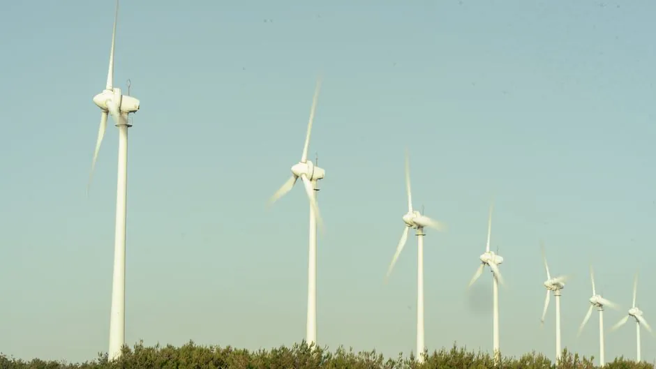
Wind-turbine universal-joint specification is governed by three hard numbers: single-joint angularity limits of roughly 45°, a speed-fluctuation cycle that repeats twice per revolution above 0°, and a recommended continuous-speed band of 1750 to 3600 RPM for elastomeric and needle-roller designs [S1][S5].
Across utility-scale yaw, pitch and main-rotor couplings, the selection pivot is angle × torque × service interval, not bolt-circle diameter. A wind turbine that is hard-coupled to the grid through a gearbox already constrains the universal joint to the speed range set by generator-pole count and gearbox ratio, and a mis-specified joint at the yaw or pitch stage is the single most common source of seasonal downtime [S2][S3].
Operating Angle, Misalignment Budget and CV Cancellation
Single Cardan (Hooke) universal joints transmit torque with non-uniform instantaneous velocity whenever the operating angle exceeds 0°, with the cycle repeating twice per revolution and amplitude rising with angle; a 30° shaft intersection produces the documented speed-variation curve shown in Fig. 6.29 of standard driveline references [S5].
For wind applications the practical fix is double-joint phasing: two single joints in a yoke-and-shaft arrangement cancel the first joint's fluctuation at the second, restoring constant-velocity output to the driven member when the yokes are in phase [S4][S5]. This is the same principle used in automotive prop shafts, and it is why yaw-drive drivelines almost universally use a paired-joint assembly rather than a single Hooke unit.
Misalignment budget differs sharply by coupling class: standard universal joints hold 15° or more of operating angle, gear couplings and spindles typically cap at 6°, and elastomeric-spider universal-joint variants trade the needle-roller service life for zero-backlash, lubrication-free operation and high lateral-misalignment tolerance [S1][S3].
Torque Density, Bearing Life and Service Factor
Bearing life is the selection line item that most often breaks in the field. Universal-joint needle-roller bearings are rated by dynamic load rating C and a target L10h figure that the designer must cross-check against the turbine's torque spectrum, including peak gust events that can deliver 2-3× nominal torque for short durations [S2][S3].
For rolling-mill duty that translates directly to wind: published mill-grade universal-joint designs target "high-impact reversing roughers and Steckel mills" with negligible backlash and radial clearance, both of which are exactly what a pitch or yaw drive needs to maintain blade-angle accuracy [S3]. Universal-joint selection must therefore start from the worst-case torque, not the mean, and apply a documented service factor for reversing, shock and start-stop duty.
Lubrication regime separates the three classes: needle-roller universal joints require periodic re-greasing, elastomeric-spider designs eliminate the lubrication step entirely because there are no moving metal-on-metal interfaces, and Oldham-style three-member couplings are usually avoided in wind because of the plastic-floating-member wear path under continuous duty [S1][S2].
Wind-Specific Duty Cycles: Yaw, Pitch and Main Rotor

Yaw drives run at low speed (typically below 50 RPM at the slewing ring) with high static torque, partial-rotation per command, and infrequent but heavy storm-lock events. Selection here favours double Cardan joints sized for stall torque rather than continuous torque, with seals rated for the nacelle's IP class [S2][S4].
Pitch drives operate at higher speed (often 1000-3000 RPM at the motor output, reduced through the planetary gearbox to the blade root) and cycle continuously with each wind-speed change. This is where needle-roller universal joints shine: they tolerate 15°+ misalignment, hold high torque density, and resist the contamination and grease-loss problems that destroy gear couplings in nacelle environments [S3].
Main-rotor drivetrains above ~1.5 MW increasingly use direct-drive permanent-magnet generators with no high-speed gearbox stage, but where a gearbox remains, the universal-joint stage between gearbox and generator coupling sits in the 1500-1800 RPM band, well within the catalogued 1750-3600 RPM recommended range for elastomeric and needle-roller designs [S1].
Comparison: Cardan vs Elastomeric-Spider vs Constant-Velocity Joints
Cardan (Hooke) single joints: lowest cost, 0-45° angle, non-uniform velocity above 0°, requires phasing or a paired unit to cancel speed fluctuation, periodic grease service [S4][S5].
Elastomeric-spider universal joints: zero backlash, no lubrication because no metal-on-metal contact, large lateral-misalignment tolerance, lower torque ceiling per envelope, ideal where maintenance access is constrained (e.g. tower-top pitch hubs) [S1][S2].
Double Cardan (paired, in-phase): constant-velocity output, retains the high-torque and 15°+ misalignment advantage of the single Hooke design, used as the default in yaw and prop-shaft service [S3][S4].
True constant-velocity (CV) ball-type joints: zero velocity fluctuation by geometry, up to 90° angle in dual-pivot designs, but precision-ground balls and curved grooves demand clean lube and tighter alignment budgets; rarely used in wind main drivetrains because the cost-per-torque ratio is unfavourable versus needle-roller universals [S4][S5].
Selection Criteria and Specification Gates

Spec gate 1, angle: confirm the worst-case static + dynamic misalignment. If the running angle exceeds 8-10°, prefer a universal joint over a gear coupling; above 15° a universal joint is the only realistic flexible option [S3].
Spec gate 2, speed band: stay inside 1750-3600 RPM for elastomeric and standard needle-roller designs unless the manufacturer has documented fatigue data for the 600-12,000 RPM range; for wind main-rotor stages this usually means a coupled step-up or direct-drive topology, not a universal joint alone [S1].
Spec gate 3, torque and service factor: size to worst-case gust or fault torque, apply a service factor of 1.5-2.0 for reversing/shock duty, and document L10h bearing life at the resulting equivalent radial load [S2][S3].
Spec gate 4, environment: nacelle IP class, salt fog, dust, and grease-retention constraints typically force sealed needle-roller or elastomeric designs; for related industrial power-transmission specification work the same gates appear in V-belt selection for steel mill drives and for mining service factors, where profiles, service factors and field traps are documented in detail V-belt selection for steel mill drives and V-belt selection for mining operations.
Spec gate 5, maintenance envelope: if the joint sits inside the hub or behind the nacelle wall, an elastomeric-spider universal-joint that removes the grease interval is usually the lower total-cost-of-ownership option despite the higher unit price [S1][S2].
Failure Modes and Field Constraints
The dominant universal-joint failure in wind service is needle-roller bearing fatigue from under-greasing, followed by seal failure and water ingress, then spider brinelling on elastomeric units that have been overloaded beyond their torque rating [S2][S3].
Phasing error is a separate failure mode: a paired Cardan assembly installed with the yokes out of phase will not cancel the speed fluctuation and will introduce torsional vibration that the upstream gearbox was not rated for, a problem well known in automotive prop shafts and directly transferable to wind yaw and pitch drivelines [S4][S5].
For a deeper dive into how a paired U-joint driveline is sized against belt and gear alternatives, see the steel-mill V-belt spec workflow, which lays out the same service-factor envelope and grease-interval trade-offs on the V-belt side of the same driveline problem steel-mill V-belt workflow.
Sourcing, Standards and Audit Trail
There is no single ISO or AGMA standard dedicated to wind-turbine universal-joint selection; the engineering references are the manufacturer's own L10h curves, the rolling-mill design papers for high-torque reversing duty, and AGMA gear-coupling flexibility data for the comparison baseline [S3].
For audit purposes a complete wind universal-joint data sheet should record: maximum and minimum operating angle, RPM band, peak and continuous torque, L10h bearing life at site conditions, grease type and interval (or "lubrication-free" declaration), seal IP class, material of yoke and spider, and the documented service factor used [S1][S2][S3].
Track the next two signals on 2026-09-19 and forward: (a) any new IEC 61400-1 design-load case revision affecting driveline component service factors, and (b) OEM-published L10h curves for needle-roller universal joints rated above 15° continuous angle, since both directly govern the selection gates above for the next turbine generation.
Detailed specification references: universal joint, expansion joint, and power cable.