
Operating a butterfly valve below approximately 20° open causes the disc edge to act as a small orifice, accelerating the fluid into a thin jet, producing cavitation, vibration, and unstable dynamic torque that the actuator cannot hold against [S1].
At the same time, a small angular change near closure moves a large fraction of the disc area into the flow path, so the valve gain (Δflow/Δangle) spikes; the control loop behaves almost binary, hunting between near-zero and a non-trivial flow instead of modulating smoothly [S1][S4]. The combined effect is poor controllability, accelerated seat and disc erosion, and a real risk of the disc moving off its setpoint under hydraulic loading [S1][S3].
What the Disc Does to the Flow at Low Openings
Below 20° open, the disc edge becomes the dominant restriction: the free area shrinks roughly with the cube of the remaining gap, and the flow separates around a sharp leading edge, forming high-velocity jets that draw local static pressure below vapor pressure [S1]. In liquid service this is the classic cavitation trigger, and in slurry service the same jet impinges solids onto the disc edge and downstream body, gouging resilient liners and eroding metal seats [S1][S3][S8].
That same uneven pressure field produces a net hydraulic torque on the disc that varies non-monotonically with angle; some openings actually develop a force that tries to drive the disc further open (or further closed) against the actuator [S1]. A positioner holding a fixed 4–20 mA setpoint can be overwhelmed by this dynamic torque, which is why field reports describe valves that "hunt," drift, or slam to a new position when differential pressure rises [S2][S6].
Why the Installed Characteristic Spikes Near Closure
Butterfly valve inherent flow characteristic is strongly equal-percentage-like, but the installed characteristic at a process plant is the product of the valve curve and the system curve, so a high-pressure-drop system amplifies the near-closure spike while a low-pressure-drop system softens it [S1]. Field data on a 0–2% opening problem showed flow jumping to roughly 8% almost immediately on crack-open, then becoming linear past 2%, a textbook signature of an oversized valve trying to throttle at the wrong end of its travel [S4].
The control consequence is that loop gain near closure becomes very large, so the same incremental step from the controller (a few percent of stroke) produces a much larger flow change than it does at mid-stroke; PID tuning that works at 30%–70% open goes unstable below 20% [S4][S6]. This is also why valve stiction, positioner deadband, and small mechanical clearances look catastrophically large at the bottom of the travel: the process is amplifying them.
Operating Envelope That Actually Works
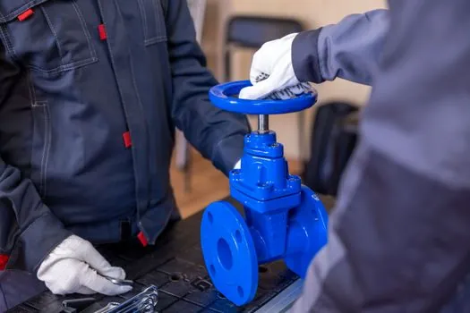
For throttling duty, the working envelope of a standard resilient-seated butterfly is generally the 30°–70° open range, where gain is moderate and disc loading is roughly balanced [S5]. Above roughly 70° the curve flattens (small flow change per degree), and below roughly 20° the curve steepens and cavitation/erosion risks dominate, so neither extreme is useful for tight control [S1][S5].
A simple comparison across three opening bands makes the trade-off explicit, based on the mechanical behaviour described in the sources:
Below 20° open: very high valve gain, cavitation likely, vibration and noise high, dynamic torque unstable, seat/disc erosion aggressive, not recommended for modulation [S1][S3][S5].
20°–30° open: marginal; some resilient-seated valves can hold for non-critical utility throttling, but metal-seated and triple-offset designs still see uneven loading and should be checked case by case [S1].
30°–70° open: the practical throttling band, predictable installed characteristic, manageable dynamic torque, and acceptable velocity for water, air, and general process service [S5].
Resilient-Seated vs Double-Offset vs Triple-Offset
Concentric resilient-seated butterflies throttle adequately in clean water and low-pressure utility service, but their rubber or PTFE liner is the weak point at low openings: concentrated jet impingement cuts grooves, and once the seat is scored, shutoff class drops [S1]. Double-offset (high-performance) designs shift the disc sealing axis so the disc only contacts the seat near full closure, reducing seat rub and widening the differential-pressure rating [S1].
Triple-offset metal-seated butterflies add an angled seat geometry that is intended for tight shutoff and higher temperatures, but the offset geometry alone does not guarantee good control: disc profile, torque coefficients, and the actuator's ability to hold position under dynamic load are product-specific and must be confirmed with manufacturer data, not assumed from the "triple-offset" label [S1]. For automated modulation all three types still need a modulating actuator, a positioner with adequate resolution, and a verification of dynamic torque across the operating envelope, not just breakaway torque [S1].
The Fix: Downsize the Valve, Change the System Curve, or Both
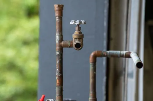
The most reliable field fix is to install a smaller butterfly on reducers so that the normal operating point sits in the 30°–70° band; a 6" line throttling clean water is often better served by a 2" or 3" valve with eccentric reducers, because the smaller valve passes design flow at a much larger opening where gain is moderate [S2]. A cascade control loop with the butterfly handling coarse flow and a smaller trim valve handling fine trim is the classic alternative when line size cannot be reduced [S2].
Other interventions target the system curve: lowering the differential pressure across the valve (by adding upstream resistance or trimming pump head) reduces the cavitation driving force and softens the near-closure gain, which is why the 0–2% test case improved noticeably when inlet pressure was reduced from 0.5–1.0 bar toward zero [S4]. For slurry and solids service, butterfly valves should generally not be used for throttling at all; the disc edge collects solids, the characteristic drifts, and the seat wears unevenly, so a different valve type or a dedicated control valve upstream is the safer call [S3][S8].
When a Butterfly Is the Wrong Choice for Control
Butterflies are a poor control choice when the application demands tight modulation below 20% of full flow, when the fluid is a flashing liquid or a slurry, when acoustic limits are tight (the disc generates broadband noise that is hard to attenuate), or when the actuator cannot source enough dynamic torque to hold position across the full pressure-drop range [S1][S3][S8]. They are also a poor choice when the piping geometry forces a long, straight run of pipe between the valve and a sensitive flow meter, because the swirling discharge from a partly open disc can distort ultrasonic meter readings, exactly the field failure mode reported at a gas-filtering and metering station [S2].
Specifiers should treat the "never below 20°" rule as a warning to size correctly, not a substitute for sizing, and should run a full Cv, cavitation, noise, and dynamic-torque check across the minimum, normal, and maximum operating points before locking the valve into modulating service [S1]. For more on the upstream flow measurement problems that a partly open butterfly can cause, see this field case write-up of a butterfly valve disturbing an ultrasonic meter at low openings, and for the broader question of how valve type affects pump and piping system curves, the related discussion of magnetic drive pump efficiency versus direct-coupled pumps is a useful adjacent reference. The core butterfly valve page also lays out the concentric, double-offset, and triple-offset geometries side by side.
Detailed specification references: open channel flowmeter, and control valve.