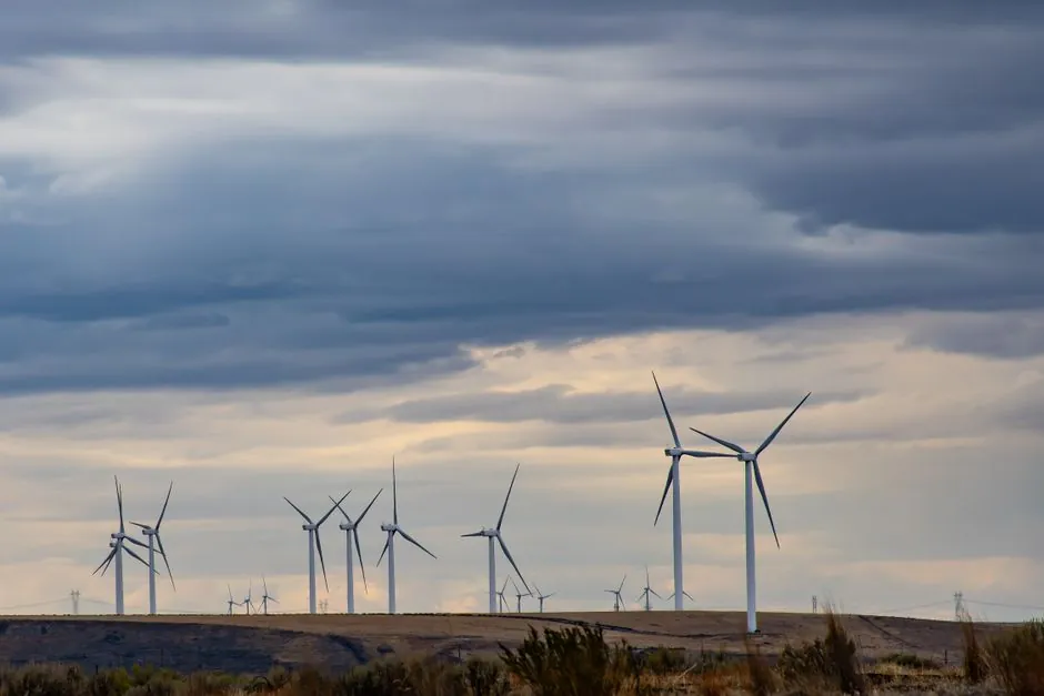
Wind turbine blade manufacturing lines integrate composite layup, resin infusion, oven/autoclave cure, root-end orbital machining, and tower-flange milling into a single flow sized for blade lengths now routinely above 52 m for land-based units and 107 m for offshore units such as the GE Haliade-X [S1]. Tooling budgets for a single new blade plant run into the tens of millions of dollars, which is why each station has to be spec-matched to the blade program rather than bought off a generic catalog.
Across the line, the equipment is grouped into four functional blocks: composite-shell fabrication (mold, infusion, cure), root-end and trailing-edge finishing, structural joining and tower/flange machining, and the heavy-lift/transport fixtures used both inside the plant and at the quayside. The composite-block machines, especially the autoclave and the resin-infusion stacks, typically dominate capex. The four blocks share little utility infrastructure: a blade mold sits on a heated concrete floor, while an orbital milling machine needs a stable rail foundation to hold the ±0.13 mm flatness blade assemblers demand [S3].
Blade construction: composite materials and layup architectures
Modern utility-scale blades are predominantly glass-fibre/epoxy laminates over a load-carrying box spar, with the suction-side and pressure-side shells bonded around internal shear webs [S2]. The spar is the primary fatigue part: the pressure-side main laminate runs in cyclic tension-tension while the suction side runs cyclic compression-compression, so resin content and fibre-architecture control at the spar directly drive fatigue life [S2].
Two process families dominate 2026 production. Wet layup (hand-placed fabric, mat or roving, resin impregnated in the tool) is the lowest-capex route, but resin content drifts with operator skill and consistency varies batch to batch, which forces heavier safety factors on the spar [S5]. Prepreg layup, where the supplier pre-impregnates the fibre, gives tight resin control but needs an autoclave or heated press for cure, raising both capex and cycle energy [S5]. For blades above roughly 60 m, most OEMs run vacuum-assisted resin transfer moulding (VARTM) or similar infusion on the shells, with prepreg only on the spar caps; this is the architecture that pushed modern land-based blade lengths past 52 m [S1][S5].
Root-end machining: the flatness gate every blade has to pass
The blade root end is a composite laminate with embedded metal blocks (each carrying a female thread) that bolts the blade to the hub; any flatness error is amplified along the blade as a mass-imbalance moment [S3]. Industry practice is to machine this face on a Wind Power (WP) orbital milling machine: the head clamps hydraulically into the blade's inner diameter, the trolley withdraws, and a hydraulically powered milling head orbits the bore to cut the root face flat [S3].
Typical achievable flatness is ±0.15 mm across the full root diameter on a properly set WP machine, with cycle time dominated by the orbit rather than the cut [S3]. For a 100+ m offshore blade, that ±0.13–0.15 mm window is non-negotiable: ISO-style balancing and field vibration limits on multi-MW hubs will not tolerate looser tolerances. Plants running mixed programs (land-based + offshore) usually keep two WP heads, one sized for the 4–5 m land-based roots and one for 6–8 m offshore roots, to avoid re-fixturing time on changeover.
Tower and flange machining: the OM-class orbital mill

Wind turbine towers ship in three or more flanged sections that are bolted on site; the bottom flange of every section and the top generator flange have to be flat to seat the pre-tensioned bolts without distortion [S3]. The standard machine for this is an OM-series orbital milling machine, set up vertically against the flange face and walked around the perimeter by a hydraulically driven head [S3].
OM machines are built in sizes matched to tower diameters, which now span roughly 4 m (small land-based) to 8 m+ (offshore monopile-topped towers). The flange is machined in situ after the section is welded, so the OM head has to work on tall, vertical surfaces with the section standing on the shop floor; stability of the rail track around the flange dictates achievable flatness, and most plants budget for a poured concrete plinth dedicated to the OM station. Selecting an OM head is similar in spec discipline to choosing precision metrology for a NDT cell: track length, repeatability, and rigidity matter more than peak spindle power.
Heavy-lift and transport fixtures: from mould to quayside
Once cured and root-machined, blades move to a finishing bay for trailing-edge trim, lightning-receptor fit, and paint, then to the shipping cradle. A 100 m offshore blade weighs 50–70 t and is handled by self-propelled modular trailers (SPMTs) with active hydraulic suspension so the blade is supported on distributed saddles that follow its curved centre of gravity. Plants that also build tower transition pieces need an electric trolley system (ETR-class) capable of moving 400–500 t transition pieces around the dock on a 90 m track, with wireless synchronised control of all four trolleys [S3].
These fixtures are not bought off a generic industrial-truck catalog. The 90 m track length, 500 t payload, and integrated hydraulic clamping/levelling make the ETR effectively a one-off for each offshore yard; lead time from order to commissioning is typically 12–18 months, which gates the start of a new blade plant more than the autoclave does [S3]. On the truck side, a single long-haul blade shipment can run over $100,000 and a short-haul $30,000–$40,000, so the in-plant handling solution directly affects the cost basis a manufacturer quotes to a developer [S4].
Process selection: a four-criteria comparison
The main process routes for blade shells (wet layup, prepreg/autoclave, VARTM infusion) line up against four decision criteria that procurement teams should benchmark before placing a P.O. [S5]
Capex per metre of blade: wet layup is lowest, VARTM is mid (dominated by infusion media, vacuum pumps, and a heated hall), prepreg/autoclave is highest because the autoclave itself is a pressure vessel with cycle-energy bills to match [S5]. Resin-content control: prepreg is the tightest, VARTM is acceptable for spar caps with good media design, wet layup is operator-dependent and the largest source of weight variation [S5]. Cycle time and throughput: wet layup is the slowest per blade because of hand layup, VARTM is faster at scale once media is staged, prepreg is the most predictable but autoclave cycle caps the daily throughput. Blade-size ceiling: wet layup runs out of ergonomic envelope above 70–80 m, VARTM is the route that took blades past 100 m, and prepreg is reserved for the highest-loaded substructures inside the blade [S5][S1].
Standards, testing, and what to anchor the spec on
Blade design and certification sit under IEC 61400 (with Part 1 covering design requirements and Part 25/27 covering structural testing of rotor blades), and most OEMs run full-scale fatigue tests to validate resin-content and fibre-architecture decisions made on the shop floor [S2]. The U.S. Department of Energy notes that blade length has more than doubled over the last two decades as the swept area per turbine has scaled with rated power, with the Haliade-X at 107 m (351 ft) blades representing the current offshore reference point [S1].
For process control inside the plant, manufacturers anchor flatness on the ±0.13–0.15 mm WP-class root-machining result cited above, and use ultrasonic or thermographic NDT on the bondline between the two shell halves and around the spar [S3]. Buyers specifying new lines should ask vendors for cycle-time-versus-blade-length data, autoclave working pressure and operating temperature, and the number of WP/OM heads per blade produced per shift; vague marketing claims from a tooling vendor are a red flag at this scale.
Two trackable signals for the next 12 months: (a) the first commercial deployments of segmented-blade architectures, which would re-shape the layup block and lower transport cost-per-MW, and (b) the wider adoption of thermoplastic resin systems, which would let OEMs drop the autoclave and run in-situ welded blade joints. Plants ordered on a 2026 spec should leave floor space and rail foundation stubs for both, since retrofitting an autoclave-bay later costs more than building it flexible from day one. For buyers looking at adjacent heavy-equipment decisions, the same spec-first logic used for plasma-cutter sizing on heavy structural work applies when selecting the cutting tools for tower internals.
For the relevant spec sheets and selection criteria, see additive manufacturing material, and linear guide.