
A bridge-construction plasma cutter sized at 60–80 A with 100% duty cycle at 40 °C and HF pilot-arc start will cut 15–25 mm structural mild-steel plate cleanly, which is the working envelope for gusset plates, stiffeners, and splice plates on typical highway-bridge steel [S4].
Plasma works on any electrically conductive metal without oxy-fuel pre-heat, so rebar, embedded plates, weathering-steel girders, and galvanised drainage components all fall inside the same machine envelope as the structural plate itself [S5]. A 6 mm mild-steel-rated cutter is broadly the entry point; a 25 mm-rated unit is the spec ceiling for most on-site fabrication work [S1][S3].
Material and Thickness Envelope for Bridge Plate
Bridge-plate work splits into three bands: 6–12 mm gusset and stiffener plate, 12–20 mm web and flange plate, and 20–25 mm splice and base plate, with thicker call-outs rare in highway work and reserved for rail or long-span signatures [S4]. A 40 A inverter covers the 6–10 mm band at recommended cut, while a 60 A inverter reaches 15–20 mm clean cut, and an 80–120 A unit handles 25 mm and above with the dross controlled through proper standoff and gas flow [S3].
Rebar and dowel bar work sits in a different physical regime: small-diameter bar (10–25 mm) cuts cleanly on a 30–40 A unit, but bridge-deck mats often mix rebar at 16, 20, and 25 mm, and the cutter head must run long lead lengths across the deck, which is where 25 ft torch reach and dual-voltage input start to matter on the jobsite [S3]. For comparison, the Plasma Cutter Sizing for Electrical Installation Work spec map handles thinner conductor and enclosure work in a lower amperage band.
Amperage, Duty Cycle, and Field Productivity
The industry shorthand is roughly 10 A per 1 mm of clean cut on mild steel for inverter-class machines, so a 60 A unit reaches 15–20 mm sever, and a 130–200 A mechanised source reaches 35–50 mm plate [S4]. On a bridge deck, a 100% duty-cycle rating at 40 °C is the relevant number, not the marketing maximum, because summer deck-plate temperatures compound with the unit's own thermal load and cut-back events will stop a long splice cut mid-run [S4].
Pilot-arc start, whether HF or contact, decides whether the torch fires on painted or galvanised plate without retracing, which matters on bridge work where galvanised drainage components and primer-coated stiffeners are common [S3][S5]. Pierce capacity typically runs 50–60% of sever capacity on conventional plasma and approaches 100% on high-definition units, and on bridge work a vertical pierce of 15–20 mm is often the first cut on a stiffener, so a high-definition torch head is the right spend when the cut feeds a welding cell rather than a coating line [S4].
Cut Quality, Bevel, and Feed-Into-Welding Geometry
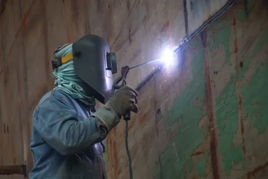
Conventional plasma leaves a 3–8° top-to-bottom bevel on 10–25 mm cuts, while high-definition plasma with constricted nozzles and nitrogen or argon-hydrogen shielding drops that to under 2° on stainless and aluminium [S4]. Kerf runs 0.8–1.5 mm depending on nozzle orifice and current, and dross on the bottom edge is the cleanest single indicator of gas-flow and standoff health on bridge plate [S4].
For bridge work that feeds into a welding cell, a 3–5° bevel is acceptable; for parts heading to a paint or galvanising line, the high-definition profile pays back in reduced rework [S4]. A practical gate: any stiffener or splice plate over 12 mm that is welded without back-gouging should be cut on a high-definition source or post-cut ground before fit-up. Buyers running both profiles should standardise on torches that accept the same plasma cutter consumables family, including tips, electrodes, swirl rings, and shrouds, so the parts shelf collapses from dozens of SKUs to a handful on a remote jobsite [S4].
Air Supply, Gas, and Jobsite Logistics
Most plasma cutters use compressed air as the plasma gas, with instrument-grade air preferred, and shop air through a desiccant filter acceptable when the alternative is no cut at all [S3]. For higher-quality cuts on stainless or aluminium, nitrogen, oxygen, or argon-hydrogen mixtures enter the picture, but on bridge work these are rare outside of architectural-grade stainless railings, where H35 / F5 shielding gas pays for itself in reduced rework [S4].
Built-in compressor units are self-contained and convenient for small jobs, but external compressor-fed machines dominate bridge work because the airflow demand of a 60–80 A continuous cut, often 4–6 CFM at 90 psi, exceeds what a portable on-board compressor delivers without duty-cycle throttling [S1]. On a remote pier or over-water staging, a tow-behind diesel compressor sized for the cutter head and a margin for nozzle blow-off is the practical configuration, and the air supply must be regulated and filtered to extend consumable life on long run days [S3].
Consumable Cost, Consumable Logistics, and Downtime
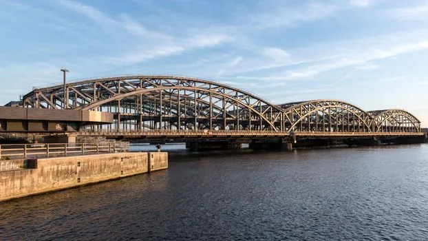
Consumables sit in the torch head: electrode, tip or nozzle, swirl ring, shield, shield cap, and retaining cup, and they wear with arc-on minutes and pierces [S4]. A 40 A drag tip on 6 mm mild steel typically lasts 60–120 pierces, while a 200 A mechanised nozzle on 25 mm stainless can exceed 800 pierces before bore erosion widens the kerf [S4].
Three levers move consumable cost: standoff distance (drag vs mechanised), gas purity (instrument-grade air vs shop air with desiccant), and pierce technique (ramp pierce vs on-plate pierce), and the wrong mix in a CNC cell can double operating cost without changing visible cut quality [S4]. For bridge-deck rebar mats, consumable stock on the truck should be sized at roughly 1.5x the planning estimate because pierces are the dominant wear mode on small-diameter bar and a single out-of-stock shift on a 1,000-pierce deck will cost more than the spare shelf space. Bridge sites also benefit from a rebar cutter or mechanical shear staged alongside the plasma head to spare the plasma consumables on clean bar cuts where the geometry permits [S4].
Selection Criteria: Handheld, Mechanised, and CNC-Ready
A field-side comparison of the three common bridge-site configurations shows the trade space clearly: a 40 A handheld inverter at 120/240 V dual voltage is the entry tier for occasional gusset and bracket work, a 60–80 A handheld or rail-mounted inverter at 100% duty is the workhorse for deck plate, stiffener, and splice work, and a 130–200 A mechanised source with CNC interface and high-definition torch is the spec for production bridge-fab shops cutting 20–40 mm plate to tight tolerance [S3][S4].
Two further spec gates matter on bridge work: cut speed in inches per minute for production runs, where modern inverter sources outpace older transformer units on the same plate thickness, and a CNC interface (RS-485 or analog input) where the shop runs nested parts [S3]. For HVAC and ductwork on bridge ancillaries, a different envelope applies, and the HVAC Plasma Cutter Spec Map covers the thinner-gauge, higher-tolerance duct side of the same cutter family. For interior finishing on bridge offices and control rooms, the Plasma Cutter Spec Map for Interior Finishing details the same machine class sized to architectural trim and bracketry rather than structural plate.
Safety, Fume, and Bridge-Site Hazards

Plasma cutting releases hazardous fumes from coatings, galvanising, and the base metal itself, including zinc from galvanised drainage components, chromium from stainless railings, and lead from primer-coated plate, and bridge work is rarely staged inside a fume-extraction booth [S5]. Ventilation, fume extraction where feasible, and respiratory protection are the standard controls, and the base-metal safety profile is a separate question from the base-metal cuttability [S5].
Pilot-arc reliability also affects safety because retriggering on a hot workpiece concentrates UV exposure on the operator's face shield and bystanders, and HF-start units can interfere with adjacent crane controls and radio on a congested deck [S3][S4]. For overhead-bridge-crane work nearby, lock-out coordination between the plasma cutting station and the crane radio is a real jobsite control, not paperwork.
Standards, Sourcing, and the Buyer Checklist
No single standard governs plasma cutter selection for bridge construction; the spec gates are: amperage and recommended cut for the target plate thickness, duty cycle at 40 °C ambient, pilot-arc start type, air supply volume and pressure, and consumable commonality across the torch family [S3][S4]. For construction-machinery-and-equipment buyers specifying plasma alongside other cutting and joining tools, the same amperage-vs-thickness rule of thumb applies across the fleet, and a 30% margin over the planned maximum thickness is a common engineering pad [S1].
Verifiable signals to track over the next buying cycle: high-definition plasma torch adoption in mid-range 60–80 A inverters, consumable-life claims published in arc-on minutes rather than pierces, and 100% duty-cycle ratings stated at 40 °C ambient rather than at 25 °C [S4]. Buyers should also confirm the cut-capacity numbers are recommended cut at usable speed, not maximum severance, and that the quoted thickness is on mild steel, because stainless and aluminium ratings run roughly 10% and 40% below the mild-steel figure on the same machine [S1].