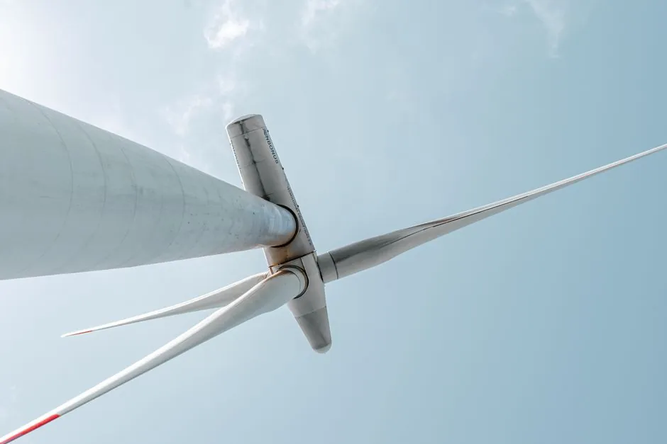
A wind turbine blade production line is built around four design gates: aerodynamic geometry, composite material stack, mold and layup equipment, and curing/finishing cells, with bend-twist-coupled (BTC) blades and flatback airfoils now treated as baseline starting points rather than R&D options [S1].
Output scales with the square of blade length, so most process engineers size the line around a target rotor diameter (commonly 80–120 m onshore, 140 m+ offshore) before locking cell counts, mold steel weight, and autoclave or oven capacity [S2].
Design-for-Manufacturability Gates That Lock the Line
Design for Manufacturability (DFM) is the upstream filter that decides what the line has to build: chord and twist distribution are first optimised for power coefficient across the tip-speed-ratio curve, then constrained by what the mold and layup cells can reliably produce in volume [S4]. TPI Composites states a DFM approach allows them to "manufacture wind blades of any design," meaning the production line is treated as a tool kit, not a single fixed recipe [S3].
Two aerodynamic choices now drive most line decisions: bend-twist-coupled blades, which twist as they bend to shed load in gusts, and flatback airfoils, which replace the sharp trailing edge with a flat or shortened edge that is easier to lay up and adds structural depth [S1]. Both were DOE / Sandia / NREL research outputs that have moved into commercial blade production lines over the past decade [S1].
Composite Stack: Fiberglass, Carbon Spar Caps, Epoxy
Blades are made from a combination of fiberglass, carbon fiber, and epoxy resins, selected for the strength-to-weight ratio each zone of the blade needs, according to a step-by-step manufacturing breakdown [S5]. The outer half of a modern blade often carries carbon-fibre spar caps or buried chordwise and spanwise stiffeners, both used to increase skin stiffness without bonding external hardware [S4].
E-glass dominates the skin and trailing-edge mat, S-glass shows up in high-stress root transitions, and carbon-fibre laminates are concentrated in the spar cap, where stiffness per kilogram matters most. For sourcing context, the glass fiber competitive landscape for 2026 is shifting as wind-energy demand pulls S-glass and high-modulus E-glass roving supply.
Process Steps That Define Cell Layout
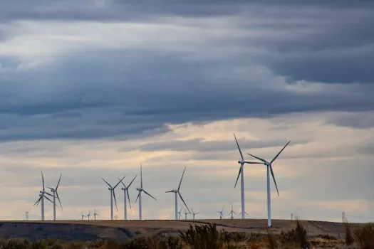
The manufacturing sequence is largely fixed: mold prep, gelcoat or skin layup, reinforcement placement, root and spar sub-assembly, main shell closure, resin infusion or pre-bagging, curing under heat and pressure, demold, trim and drill, root hardware install, balancing, surface coat, and final NDT [S5]. Each step sets a cell footprint and a takt time, and the slowest cell (usually layup or curing) sets the daily blade throughput.
Tooling choice follows the same logic: high-strength steel molds are used for high-volume programmes, composite molds for prototypes and shorter runs, and mold life is one of the largest capital line items amortised across blade count [S5]. Material handling between cells uses overhead cranes, rail-bound trolleys, and increasingly automated guided carts because a 70–100 m blade cannot be manually carried between stations.
Cost Model: Labor, Material, Overhead, Business
A design-driven wind blade manufacturing model published in Renewable Energy organises every line decision around four cost categories: labor, material, overhead, and business, with labor itself split into direct, scrap, consumable, and indirect [S2]. The model adds cost factors most prior techno-economic models missed, including insurance, warranty, property and income taxes, salaried staff, and profit, so capex and process changes can be evaluated on the same cash-flow basis [S2].
The paper's key finding is that the industry has cut blade cost per kilogram largely without large-scale automation, because no comprehensive cost model existed to predict the impact of concurrent design and process changes, which kept automation business cases under-built [S2]. For a process engineer, that maps directly to line design: each new layup robot, infusion rig, or curing oven must clear the four-bucket model, not just a labor-rate spreadsheet.
Comparison: Manual vs Semi-Automated vs Fully Automated Lines
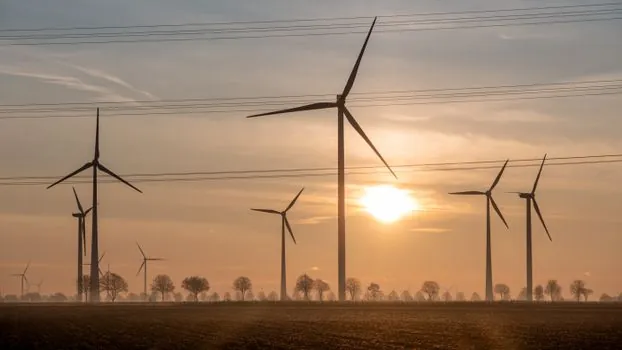
Three line archetypes compete for new programmes, and the right pick depends on annual blade count, blade length, and labour cost. Manual lines dominate prototyping and short runs because they accept design changes with no retooling; semi-automated lines add cutting, kitting, and infusion mechanisation around hand layup; fully automated lines integrate robotic fibre placement, automated root drilling, and inline NDT for serial offshore blades over 80 m. [S1]
Capex per line scales roughly with the largest part: a single 100 m blade mold plus curing oven typically anchors a third or more of the line budget before robots are counted.
QA, NDT, and Standards Anchoring the Line
Quality assurance is built into every cell, not added at the end: each blade is NDT-tested with ultrasound and X-ray for internal defects, then dynamically balanced for weight distribution before release [S5]. Surface finishing includes a UV- and moisture-resistant coating and a smoothness pass that directly affects aerodynamic drag and annual energy production.
Standards commonly cited for blade lines include IEC 61400 (wind turbine design requirements family) for blade structural and fatigue tests, ISO 9001 for line-level quality systems, and DNVGL-ST-0376 for rotor blade design where offshore certification applies; site-specific standards vary by buyer, so the line's QA cell needs to log against the buyer's checklist, not just internal ITP. Logistics planning also belongs in the line design: blades are large, fragile, and usually moved with specialised trailers and cranes, so gate size, road access, and laydown area must be in the civil scope from day one [S5].
When the Line Design Fails, and What to Watch Next
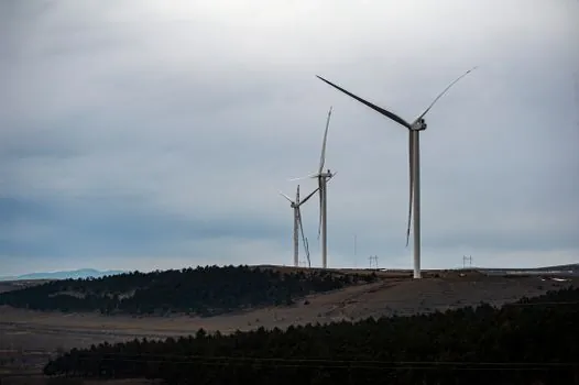
The most common failure modes are upstream: an aerodynamic shape that is aero-optimal but layup-hostile, a mold change cycle that erodes OEE, or a cure schedule that bottlenecks the cell. Skipping the DFM gate is the single biggest root cause of cost overruns, because downstream cells absorb geometry they were not laid out for, which the four-bucket model will surface quickly if it is used at the design stage [S2].
Two signals are worth tracking into late 2026: the rate at which offshore programmes above 15 MW commit to fully automated lines, and whether composite foundries begin offering pre-kitted, pre-cut reinforcement packages that let manual lines behave like semi-automated ones without the robot capex [S2][S5]. For plants that already run multi-megawatt blades, the immediate practical move is to plug insurance, warranty, salaried staff, and profit into the existing cost model, because those four lines alone typically flip the business case on a proposed layup upgrade [S2].
For component-level specifications, see turbine flowmeter, molding line, and automatic molding line.