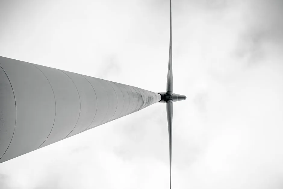
Wind turbine blade process control in 2026 is built around a closed loop that fuses blade-surface strain gauges, root bending-moment load cells, and tower-top accelerometers with a controller that drives electromagnetic torque and individual pitch angle to hold fatigue damage inside a preset envelope [S2][S5].
The driver is economic, not academic: NREL benchmarks the annual maintenance cost of an onshore turbine at roughly USD 17,000 versus USD 46,000 for an offshore unit, so any sensor stack has to earn its capital cost by cutting unplanned downtime and blade replacement events [S2]. Global installed wind capacity reached 117 GW added in 2024 with China at 328.4 GW cumulative and the US at 132.2 GW, which means the fleet exposed to these control loops is now overwhelmingly multi-megawatt, offshore-exposed, and maintenance-expensive [S2].
Sensor stack on the blade: what gets measured, where, and why
Sandia's rotor blade instrumentation work treats the blade as a distributed measurement problem: surface strain gauges along the spar cap capture flapwise and edgewise bending, root-region strain bridges feed the load-moment estimator, and surface-mounted acoustic-emission or fibre-Bragg sensors are added to catch crack initiation before it reaches the visible surface [S1][S8]. A typical instrumented coupon uses a maximum-strain design between hub and blade so the gauge sits in the highest stress gradient and returns a strong signal during transient gust events [S8]. Sandia's programme states the goal plainly: a working set of in-service load sensors that "shine light on the unknowns of how the wind" actually loads each blade in the field, rather than trusting aeroelastic models alone [S1].
For factory-acceptance and full-scale validation, BLAEST in Aalborg routinely static- and fatigue-tests blades past 80 m with multi-channel strain, displacement, and modal-acquisition systems, and the published test programmes confirm that channel counts in the 50-100 range per blade are now normal for prototype campaigns [S7]. Inside a manufacturing cell, the same measurement philosophy shows up as mould-pressure and cure-temperature probes on the pressure shell and main shell tooling, with process-control loops chasing tighter vacuum and exotherm envelopes [S6].
Control loops: from torque and pitch to life-aware setpoints
The classical wind turbine control surface has three actuators worth naming: generator torque (fastest, used below rated wind speed for speed capture), collective pitch (used above rated to limit power and untwist the blade for load relief), and individual pitch (per-blade, used to counter once-per-revolution asymmetries and tilt/yaw moments) [S5]. National Instruments' control reference breaks wind turbine control into start-up, partial-load, full-load, and cut-out regions, with the partial-to-full transition centred on the rated rotor speed where torque control hands off to pitch control [S5].
The newer layer on top is a remaining-useful-life outer loop. The 2024 strategy paper from PMC partitions the controller into an inner load-shedding loop and an outer loop that runs a Paris crack-propagation model combined with a particle-filter state estimator, then feeds the inner loop setpoints that balance pitch-actuator fatigue against blade crack growth [S2]. The control target is a predefined "remaining useful life" passed down by the O&M strategy, and the practical result is a controller that deliberately throttles itself as crack length approaches the maintenance threshold instead of waiting for a structural event [S2].
Process-control engineers working on the process control side will recognise the structure: a slow outer loop (damage accumulation, sampled at 1-10 Hz at most) driving a fast inner loop (torque and pitch, executing at the converter's kHz-range current-loop rate) [S5][S2]. The instrumentation discipline that ties the two together, especially the periodic re-zeroing of strain bridges and the traceable calibration of torque and pitch feedback, is covered under the process calibration reference framework used across heavy-industrial plants.
Selection criteria: matching the sensor spec to the loop it feeds
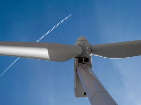
Three engineering criteria drive the spec for a blade-instrumentation package: bandwidth, survivability, and data integrity. Bandwidth matters because flapwise bending modes on a 70-80 m blade sit in the 0.5-2 Hz range, while edgewise modes and tower-passing loads push into 3-5 Hz, and acoustic-emission crack-initiation events live above 20 kHz, so a single DAQ chassis rarely covers all three without split sampling [S5][S1]. NI's modular PXI and CompactDAQ families are the de-facto reference for stacking strain, vibration, and temperature modules on the same timing backbone, and the product taxonomy explicitly separates strain, pressure, force, sound, and vibration into distinct module classes rather than treating them as one analog input [S5].
Survivability is the off-shore differentiator. Salt spray, ice, and a 25-year service life push designers toward fibre-Bragg arrays over resistive foil gauges, hermetic strain-gauge installations potted in marine-grade epoxy, and lightning-certified cable routing along the lightning-reception system on the blade tip [S1][S4]. Installation tooling matters as well: blade clamps and root-connection fixtures have to be torque-traceable and proof-loaded, because a slipped root fixture during a static test destroys both the blade and the calibration of every gauge bonded to it [S4].
Data integrity closes the loop. The Sandia instrumentation philosophy is explicit that field-grade load data only becomes useful if it is time-synchronised across strain, accelerometer, wind, and SCADA channels, which is why modern systems use IEEE 1588 PTP or GPS-disciplined timestamps instead of free-running DAQ clocks [S1]. For turbine flowmeter-class metering on the hydraulic pitch and lock-pin systems, the same timing discipline applies so that pitch-rate commands can be correlated with hydraulic flow and pressure transients during a cut-out event.
Who this is for, and where it is overkill
Life-aware, dual-loop control with distributed blade sensing is built for multi-megawatt, offshore-exposed turbines running in turbulent sites where a single blade replacement can run into seven-figure costs and a jack-up vessel slot [S2][S1]. It is the right answer for fleets in IEC wind class IA and above, for sites with significant wake-induced turbulence, and for any operator who has already absorbed at least one catastrophic blade failure event.
It is overkill for sub-1.5 MW legacy onshore turbines on flat agricultural sites, where a basic collective-pitch controller with a single anemometer and rotor-speed feedback has been delivering acceptable availability for two decades, and the marginal cost of per-blade sensing and individual pitch hardware is hard to recover [S5]. It is also the wrong tool for grid-forming or synthetic-inertia duty, where the relevant control surface is the converter's voltage/frequency loop rather than the mechanical load loop on the blade.
Process control vs structural testing: two different rig philosophies
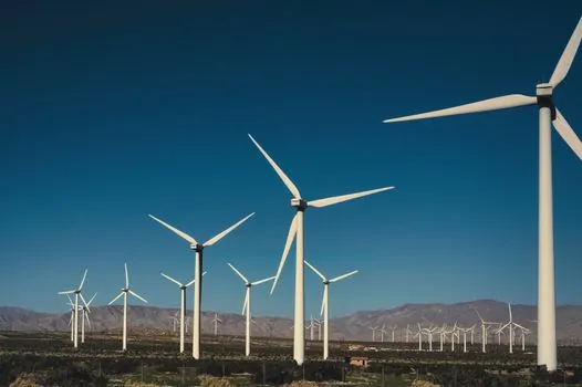
Factory and prototype work uses a different rig philosophy from in-service control. A BLAEST-class full-scale blade test rig exercises the blade as a cantilevered beam with hydraulic actuators at the root for flapwise and edgewise loading, running fatigue cycles in the 10^5-10^6 range with continuous strain, displacement, and acoustic monitoring, and the load is shaped to a target load-spectrum histogram rather than a single sinusoidal amplitude [S7]. The control objective here is structural: prove the blade survives the design spectrum, and qualify the resin system, root laminate, and trailing-edge bond against IEC 61400-23-style test protocols.
In-service process control on the operational turbine inverts that priority. The control loop does not try to push the blade to failure; it tries to keep flapwise and edgewise damage increments inside a damage-tolerance budget per megawatt-hour produced, and it does that by closing on rotor speed, pitch angle, and torque while watching the strain signal for changes in the modal damping signature that hint at a leading-edge erosion or delamination event [S2][S5][S1]. One is a destructive-test discipline run over weeks; the other is a feedback-control discipline run over decades.
Comparison of the main control options for a 2026 utility-scale turbine
Four control architectures are competing for the same multi-megawatt slot, and the trade-off lines up cleanly. (1) Conventional torque + collective pitch, cheapest to implement, baseline availability, no per-blade load relief. (2) Torque + collective + individual pitch (IPC), adds 1P and 2P load reduction, modest cost adder, supported by every major turbine OEM. (3) Life-aware dual-loop control with distributed strain sensing, adds Paris/particle-filter outer loop, supports remaining-useful-life scheduling, higher sensor and software cost [S2]. (4) Active aerodynamic devices (trailing-edge flaps, micro-tabs) on the blade, highest load-reduction potential, highest actuator and reliability risk, still mostly at TRL 6-7 outside a few demonstrator fleets [S1].
The decision pivots on three numbers: expected annual energy production loss per 1P load event, target availability (typically 96-98% for offshore), and the operator's tolerance for unscheduled maintenance. A fleet that has already paid for one emergency blade replacement will recover the cost of option 3 inside a single avoided event; a greenfield site with a strong service contract may rationally stop at option 2 [S2][S5].
Limitations, failure modes, and where the loop falls apart
The dominant failure mode is not a controller bug; it is a sensor that quietly went bad. A strain gauge that has lost its bond, a fibre-Bragg array with a cracked splice, or a root load cell that has drifted out of calibration will feed the outer loop a falsely optimistic load signal, and the controller will dutifully push the blade closer to the damage threshold it thinks is still safe [S1][S2]. Sandia's published view is that the instrumentation set has to be designed for in-situ validation, not just for initial characterisation, which is why redundancy at the spar cap and periodic modal-identification tests are baked into the programme rather than added on after a failure event [S1].
The second limitation is computational. Particle-filter damage estimation runs cleanly in a research setting but has to be reduced to a fixed-point or at most a few-Hz real-time task to run on a turbine controller, and that down-sampling trades off model fidelity against loop stability [S2]. The third limitation is the lightning and electromagnetic environment inside the nacelle: a controller that decides to dump torque based on a noisy strain reading can trip the converter, so the signal-conditioning chain typically includes analogue anti-aliasing, optical isolation on the blade-side DAQ link, and software rate-limiters on the torque-demand output [S5].
Procurement and production-planning context for plants adding this kind of line is detailed in the Wind turbine blade manufacturing equipment: a 2026 spec-first selection map reference, while fleet-level capacity decisions sit in the Wind Turbine Blade Production Capacity Planning: 2026 Spec Map article. Material-side cost pressure on the carbon-fibre feed that goes into every instrumented spar cap is tracked in Carbon Fiber Demand 2026-2030: Sizing the Doubling Across Fiber, Composite, and.
Standards, sourcing, and what to verify before signing a spec
Design loads and control-loop safety functions sit inside the IEC 61400-1 design-load-case framework for land and offshore turbines, with IEC 61400-23 covering full-scale blade testing and IEC 61400-25 defining the SCADA communication surface that the controller's outer loop logs into [S5][S1]. For the manufacturing cell, blade moulds and cure profiles are typically validated against internal OEM process specs that derive from the same IEC framework plus the resin system's material datasheet [S6]. Functional safety of the pitch and torque systems is handled under IEC 61508 / IEC 61511, with safety-integrity levels set by the consequence of a runaway-pitch event.
The procurement ask that saves the most rework is to require, in writing, the channel count, sample rate per channel, synchronisation method, gauge type and bonding procedure, and a documented calibration interval for every transducer in the loop, plus a failure-mode simulation that shows how the controller behaves when each sensor drops out in turn [S1][S5]. The cost of that paperwork is trivial; the cost of discovering, three years into a service contract, that the strain signal was never time-aligned with the SCADA torque command is not.
Next signals to track: the IEC 61400-1 revision status for the next load-case update, the release cadence of OEM life-aware control firmware, and the published availability delta between fleets running individual pitch and life-aware dual-loop control on comparable IEC wind-class sites [S2][S5].