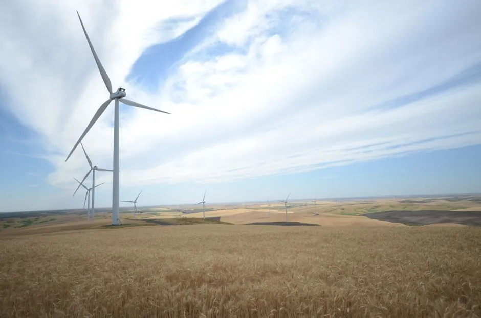
A wind turbine gearbox converts the rotor's low-speed, high-torque input into the high-speed rotation required by the generator, with thermal management of bearings and gear meshes the dominant design constraint, per ZF Wind Power's published simulation work [S5].
Process control and instrumentation on that drivetrain therefore centers on three measured variables: lubricant flow and pressure, bearing and housing temperature, and vibration at the planetary and high-speed stages, all of which feed the turbine controller and the condition-monitoring (CMS) layer described in Transmission Dynamics' monitoring brief [S4].
Drivetrain configurations and where the gearbox instrumentation sits
Operators choose between geared, direct-drive, and hybrid drivetrains, with each topology shifting the instrumentation load toward different sensor types [S2]. Geared turbines carry a multi-stage speed increaser, typically a planetary first stage plus one or two helical stages, and therefore require full bearing, gear-mesh vibration, and lubrication instrumentation.
Direct-drive turbines remove the gearbox and shift the sensing burden to the generator air gap, stator windings, and converter, so the process-control loop in direct-drive units is dominated by electrical sensors rather than mechanical ones. Hybrid or integrated designs carry a partial gearbox plus an integrated generator, and demand both lubrication instrumentation on the gear side and torque/thermal monitoring on the generator side.
Gear topology inside the gearbox (planetary, helical, bevel, spur, worm) changes the failure mode distribution, with planetary stages most exposed to planet-carrier and rolling-element bearing wear and helical stages most exposed to gear-mesh loading, and the sensor placement and alarm thresholds follow that distribution [S2].
Lubrication loop: flow, pressure, and temperature as the primary control variables
The lubrication circuit is the single most important continuous process loop in a wind turbine gearbox, because gear-mesh and bearing heat rejection depends on it, and ZF Wind Power's Simcenter Flomaster case study describes a network that may contain hundreds to thousands of small flow components generating distributed pressure losses [S5].
A typical gearbox lubrication instrument package includes a gear-pump-driven loop with a filter block, a cooler (often air-to-oil on a fan stack, or water-cooled on larger units), and a reservoir with breather, and the standard measurement set on that loop is flowmeter at the pump discharge, pressure transmitter upstream and downstream of the filter, differential pressure across the filter element for clogging detection, and temperature transmitters at the pump discharge, cooler inlet, and bearing-sump return.
Filter ΔP alarms are commonly set against a clean-element baseline, with a typical switch threshold in the 0.8 to 2.0 bar range depending on system design pressure, and flow switches on the spray bars to the high-speed bearings act as a hard interlock to prevent operation without lubrication. Process-control engineers treat these as safety-instrumented functions rather than indicating instruments, because loss of oil flow to a planetary stage leads to rapid heat soak and bearing distress.
On the cooler side, the inlet and outlet temperature transmitters close the heat-balance loop, and the controller modulates fan speed, water flow, or bypass valves to keep the gearbox bearing-sump temperature in a target band, typically 60 to 80 °C steady-state, with high-temperature trips in the 85 to 95 °C range that command shutdown. Inline particle counters and online oil-quality sensors (dielectric constant, water activity, viscosity) are increasingly layered on the reservoir return line for lifetime-extension programs [S4].
Vibration, strain, and bearing-condition instrumentation
Vibration measurement on a wind turbine gearbox typically uses accelerometers mounted on the planetary carrier housing, the high-speed stage bearings, and the generator-side coupling, with shaft-relative proximity probes or encoders for torsional and speed data [S1].
Standard CMS practice acquires both high-frequency enveloping (for bearing inner- and outer-race defect frequencies) and lower-frequency gear-mesh tones (planetary stage sun-to-planet and ring meshing, plus high-speed stage mesh), with alarm bands normally set against a baseline of a few g RMS on the housing and stepped escalation bands rather than a single hard limit. Velocity RMS in the 4 to 10 mm/s range is a common alert boundary on gear housings, with severity bands rising into the 11 to 20 mm/s range.
Strain gauges and torque transducers between the main shaft and the gearbox input, plus blade-root and tower-base strain, are the input side of the load-validation loop, and these channels feed the controller's collective-pitch and torque setpoints, as well as the digital-twin model that drives sensor placement and condition alerts on the gearbox itself [S4]. Transmission Dynamics describes a UK role in the USA-UK Bilateral Collaboration Consortium's "Optimal Sensor Placement for Physics-Based Digital Twins" project aimed at the offshore wind fleet.
Bearing temperature is monitored through RTD or thermocouple elements embedded in the bearing housings or, in newer units, in the bearing outer ring itself, and these signals are usually hardwired to the turbine PLC with a separate, faster loop than the gearbox-sump temperature used for lubrication control.
Controller, SCADA, and data architecture
At the controller level, a wind turbine's main PLC (typically a Bachmann, Beckhoff, or B&R platform) closes the loops for pitch, yaw, torque, and gearbox lubrication, and exposes the same signals northbound to the SCADA system and to the CMS server [S1].
National Instruments' wind-turbine control reference describes the standard three-loop hierarchy: a fast inner loop on converter torque (millisecond response), a mid-loop on pitch and generator speed (sub-second to one-second response), and an outer supervisory loop on power output and curtailment. The gearbox lubrication and temperature interlocks sit alongside the pitch and torque safety chain, not inside it, and are normally hardwired to the safety PLC so they remain functional even if the main controller is faulted.
Data from the gearbox vibration, oil, and temperature channels is typically published by the CMS as OPC UA or Modbus TCP northbound to the operator's fleet SCADA, and the same database feeds longer-horizon analytics, including the multi-scale condition-monitoring approach published by Castellani et al., which blends long-term trend models with short-term anomaly detection on the same drivetrain signals [S7].
For lifetime-extension programs on aging fleets, the trend is toward wireless sensor overlays (battery-powered vibration and strain nodes) bolted onto existing cable runs rather than rewiring the tower, a strategy Transmission Dynamics markets explicitly for operators weighing "replace or extend" decisions on legacy units [S4].
Selection criteria and a comparison of the main instrumentation families
Process-control instrumentation on a wind turbine gearbox falls into four functional families, and the selection question is which signals are hardwired safety-instrumented functions versus which are condition-monitoring inputs. The lubrication loop instruments (flow, pressure, temperature, ΔP) are normally the former, while vibration, acoustic-emission, and oil-quality sensors are the latter. [S2]
On the lubrication family, typical picks are a gear-meter or turbine flowmeter on the pump discharge for the 30 to 150 L/min flow range common to multi-MW units, a process-control pressure transmitter on the manifold block for 0 to 25 bar system pressure, an RTD or thermocouple on each bearing-sump, and a differential-pressure switch across the filter element.
On the vibration family, standard picks are IEPE accelerometers (100 mV/g class) for housing vibration, a shaft-relative eddy-current probe on the high-speed shaft for orbit, and a shaft encoder or Hall-effect speed sensor for 1/rev and gear-mesh order tracking. A side-by-side criteria comparison: lubrication-loop instruments give high signal-to-noise, slow response (seconds), and direct physical meaning (°C, bar, L/min), while vibration instruments give fast response (kHz) and early fault detection but require heavy post-processing to convert to a maintenance action.
On the gearbox housing itself, embedded or surface-mount RTDs on the bearing housings form a third family that bridges the two, because the signal is a physical variable like the lubrication family but the failure mode being detected (bearing distress) is the same as the vibration family. For all three families, the construction-machinery-and-equipment class norms for harsh-environment enclosures, cable glanding, and surge protection apply, given the nacelle vibration, temperature swing, and tower-shadow lightning exposure.
Standards, failure modes, and limits to watch
Wind turbine gearbox instrumentation is governed indirectly through the type certification framework applied to the whole turbine (IEC 61400-1 design requirements, IEC 61400-25 communications), while the instrumentation on the lubrication loop is selected against the same functional-safety principles that apply to other process plant, with hardwired SIL-rated pressure, flow, and temperature switches feeding the safety PLC. [S2]
Common failure modes that the instrumentation must catch are: filter clogging (ΔP rising, flow falling, bearing temperature rising), oil cooler fouling (cooler ΔT collapsing while sump temperature rises), pump degradation (flow falling with intact ΔP and no filter alarm), planetary stage bearing distress (vibration enveloping on planet-pass frequency), and high-speed stage gear-mesh wear (sideband growth around gear-mesh tone in vibration spectra) [S2][S7].
A practical limit to the gearbox process-control design is that temperature and pressure signals are lagging indicators, with typical time constants of tens of seconds to minutes, while vibration signals are leading indicators but noisy and prone to false alarms in a vibrating nacelle, so the control and monitoring architectures have to be tuned together rather than specified independently [S1][S4].
For related sizing context on the gearbox itself, see the 10 MW-class capacity-planning brief; for the lubrication loop's flow-measurement hardware options, see the TDR level-meter and flowmeter supplier map.
2026 signals worth tracking
Two trackable signals stand out: first, the rate at which new offshore units ship with a fully integrated CMS plus digital-twin interface in the turbine controller, rather than a retrofitted CMS server, as documented in ZF Wind Power's simulation-driven design work and Transmission Dynamics' sensor-placement consortium [S4][S5].
Second, the maturation of wireless, battery-powered vibration overlays for lifetime-extension programs on legacy fleets, where the deployment scale across the 2010-era installed base will determine whether the wireless overlay becomes a standard option or stays a niche retrofit [S4].