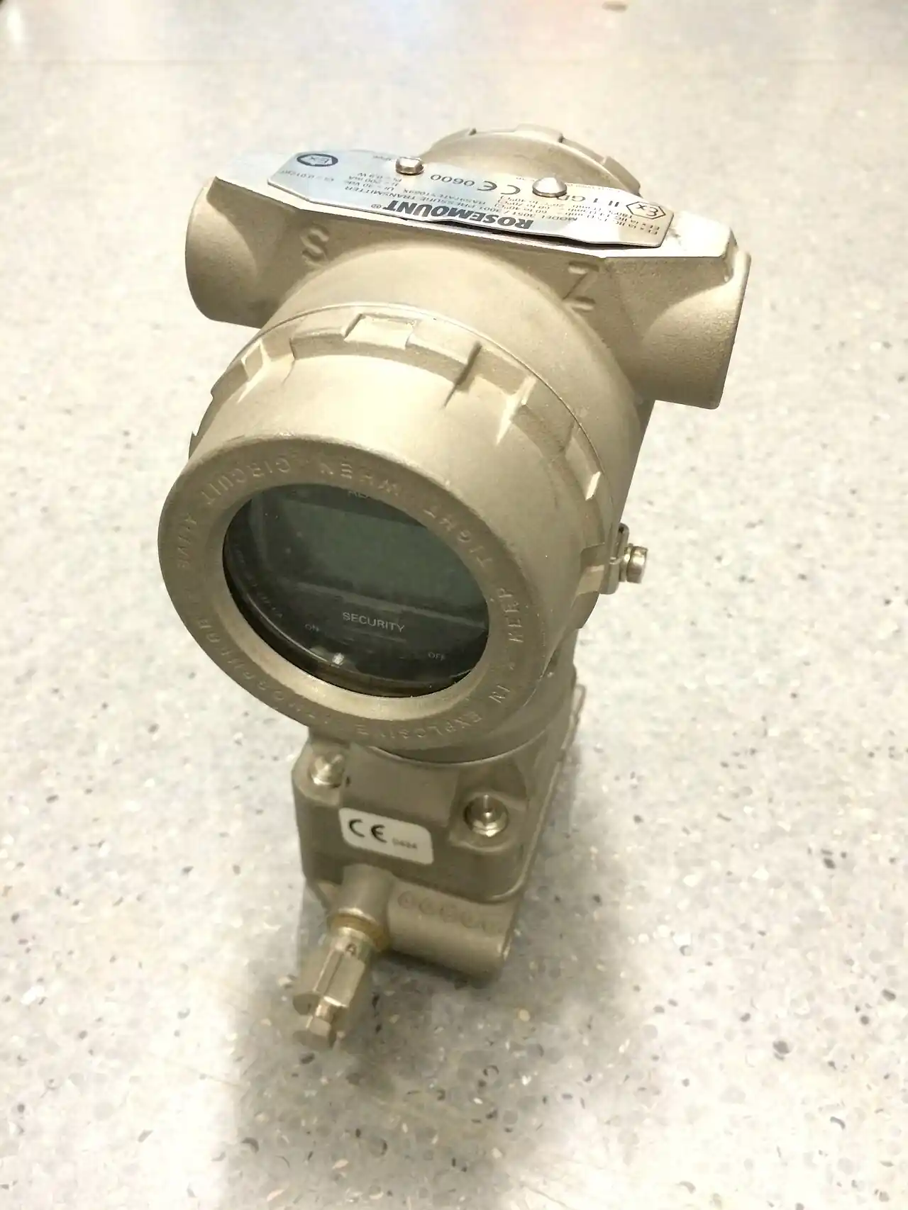
A diaphragm seal is a pressure-tight isolation device that places a thin flexible metal membrane between a hostile process fluid and a pressure instrument. The space behind the membrane is filled with a hydraulic fluid, so process pressure deflects the diaphragm and transmits through the fill to a pressure transmitter, a pressure gauge, or a differential pressure transmitter mounted directly or at the end of a capillary line. The process fluid never reaches the instrument. The device answers one standing procurement problem: how to measure pressure reliably in corrosive, viscous, crystallizing, hot, freezing, or sanitary service without destroying the measuring element.
The specification work divides into five decisions: seal body type and process connection, diaphragm material against the chemistry, fill fluid against the temperature span, capillary length and bore against response time, and the instrument span against the fill-fluid thermal effects that shift zero. Buyers who treat the seal as an accessory routinely buy the wrong fill fluid or an overlong capillary and inherit a slow, drifting loop. This page works each decision the way an instrument engineer writes the spec: with material limits, temperature windows, response numbers, and the exact lines an RFQ must carry.
This page treats the diaphragm seal as a hydraulic and metallurgical component: how flanged, threaded, pancake, and inline bodies divide the family, which fill fluid covers which temperature window, how capillary bore and length set response time, how fill-fluid thermal expansion shifts span and zero, and what an RFQ must state so the assembly that arrives holds calibration rather than merely the catalog description.
Chapter 1 / 06
What a Diaphragm Seal Is and What Is Being Decided
Every pressure measurement task starts with a wetted boundary question: what fluid touches the sensing element. A bare pressure sensor or gauge connects its Bourdon tube or cell directly to the process. In clean oil, air, or water service that is correct and cheapest. In hydrochloric acid, polymerizing monomer, molten sulfur, tar, chlorine, or food slurry, direct contact means a destroyed instrument, a plugged port, or a contaminated batch. The diaphragm seal exists for those services. It is not a valve, not a pump, and despite the shared word not a diaphragm pump or a diaphragm valve: those are flow devices. The seal is a measurement accessory whose only job is to move pressure across a wall without moving fluid through it.
The purchase decision is therefore an isolation decision, and it has exactly five moving parts. First, the seal body: flanged, threaded, pancake, or in-line flow-through, chosen by process connection and drainability. Second, the diaphragm itself: a disk typically 0.05 to 0.1 mm thin in the sealing zone, whose material must survive the chemistry at the process temperature. Third, the fill fluid: silicone oil, halocarbon, glycerin, or specialty fluids, each with a working window and a cleanliness grade. Fourth, the transmission path: direct coupling or capillary at 1 to 15 m, whose bore and length set how fast the loop answers a step change. Fifth, the instrument behind it: a gauge pressure transmitter, an absolute pressure transmitter, a gauge, or a differential pressure transmitter, whose span must absorb the thermal zero shift the fill fluid contributes.
What is actually being decided is a trade between protection and measurement quality. The seal protects absolutely but costs accuracy and speed. Fill volume adds thermal expansion error; a diaphragm has a finite stiffness that consumes part of the instrument span; a capillary adds transport delay measured in seconds, not milliseconds. A well-specified assembly on a distillation column holds 0.2 to 0.5 percent of span in practice; a badly specified one on the same column drifts 2 percent with each ambient temperature cycle. The engineering content of the purchase is knowing which lever causes which error, and the rest of this page is organized around exactly that.
One scoping note: the seal family also covers level and flow duties. A bubbler-free hydrostatic tank reading uses a flanged low-side seal; an orifice plate flowmeter on tarry fluid measures differential pressure through paired seals on the corner taps. The same five decisions apply whether the protected instrument is a pressure transmitter, a level transmitter, or a flow differential unit, so this page uses pressure service for examples and the rules transfer directly.
Chapter 2 / 06
How Isolation Works: Mechanics and Hydraulics
The diaphragm is a clamped circular membrane, commonly 25 to 100 mm in working diameter depending on body size, with a corrugated or nested-ripple profile that linearizes travel. Process pressure p pushes on the process side; the fill column pushes back. Equilibrium is reached when the diaphragm has displaced a volume of fill equal to the volume the instrument side accepts: the small bore of a gauge Bourdon tube unwinding, or the displacement cell of a transmitter, typically 0.05 to 0.3 cubic centimeters. Because the diaphragm is thin and corrugated, the pressure difference across it at rest is a small fraction of a percent of reading; the assembly behaves hydraulically like a stiff liquid link rather than a spring.
Two consequences follow. First, the fill loop must be full and gas-free at commissioning; a single bubble makes the assembly compressible and produces temperature-dependent errors many times the diaphragm stiffness error. Vendors vacuum-fill and weld or bolt the fill port under vacuum, which is why field refilling is a workshop job, not a maintenance-line job. Second, the fill fluid expands with temperature. A 15 m capillary of 1 mm bore holds about 12 cubic centimeters of fluid; warming that column 30 deg C expands it by roughly 0.3 percent in volume, and the displaced volume has nowhere to go except into moving the instrument. The result is a zero shift that a well-designed assembly partially balances by diaphragm compliance, and a poorly designed one delivers to the display as drift. Vendors publish the number as a temperature effect per 10 deg C per meter of capillary, and it is the first thing to check on the datasheet.
Response time is a laminar-flow problem. The fill moves through capillary bores of 0.7, 1.0, or 2.0 mm typical inside diameter, and the hydraulic resistance scales with the fourth power of diameter while delay scales with length. Practical numbers from vendor step-response curves: a directly coupled seal reaches 90 percent of a step in well under 1 second; a 3 m capillary at 1 mm bore answers in 2 to 4 seconds; a 10 m run at 0.7 mm bore can exceed 30 seconds. On a vessel pressure alarm that penalty is irrelevant; on a compressor surge loop it is disqualifying, and the correct answer there is a remote seal with the transmitter at 1 to 2 m, not a longer line. The bore choice also interacts with thermal error: large bore carries more fluid volume and more expansion error, so the 2 mm bore belongs on viscous-fill, short-run duties, not on long reaches.
The diaphragm itself has a performance envelope. Above a working diameter-specific pressure, typically 40 to 100 bar depending on size, the membrane becomes stiff relative to the instrument and the compliance benefit shrinks; very high static pressures are better served by a smaller diaphragm in a heavier body. Below roughly 0.4 bar absolute the diaphragm and fill stiffness set the floor on measurable span, which is why deep-vacuum service specifies a large-diameter, thin, nested-ripple element. The stiffness also sets the minimum span an assembly can hold: put a 1 bar span behind a small stiff diaphragm and the diaphragm consumes a visible fraction of it, appearing as degraded linearity near zero. Vendors summarize all of this in a permissible span table per seal size, and reading that table against the intended transmitter span is the core of Chapter 4.
Finally, the hydraulic loop is closed by the instrument mount. Direct mounts bolt the seal to the transmitter flange with the fill face to fill face, zero added volume. Remote mounts run the capillary to a second seal at the transmitter, or in differential service to two process taps. On a differential pressure transmitter installed across an orifice run on heavy crude, both corner taps get seals and often a 3-valve or 5-valve manifold dimensioned to IEC 61518 so the block-and-bleed geometry matches the instrument face. That standard exists precisely because seal and manifold mating dimensions were once a bolt-pattern lottery; specifying it in the RFQ removes an entire class of site mismatch.
Chapter 3 / 06
Seal Types, Materials, and Duty Boundaries
The four body archetypes divide by process connection and by what they do to the flow path. The flanged seal welds or machines its diaphragm into a flange that bolts to a pipe or vessel nozzle, matching ASME B16.5 or EN 1092 drilling in class 150 through 600 as supply requires. It is the default for corrosive and crystallizing duties because the wetted cavity has no pocket a thread can hide fluid in, and it survives full line pressure. The threaded seal screws into a 1/2 NPT or M20 tapping; it is compact and cheap, right for clean viscous fluids, and wrong for anything that plugs a crevice. The pancake or clamp-in seal sandwiches the diaphragm between existing flanges, sandwich-style, and suits sanitary tri-clamp lines and retrofit work where no welded nozzle exists. The in-line flow-through seal splices into the pipe itself, letting the process sweep the cavity, which is the correct geometry for polymerizing or solidifying fluids that would dead-end any other type.
Material selection is chemistry at temperature, and the standard ladder is well established. Stainless steel, 316L by default, covers water, steam, oils, and most neutral chemistry to about 40 bar and 400 deg C depending on body rating. Alloy 276 (Hastelloy C-276) buys resistance to wet chlorine, hypochlorite, and sour gas with acetic acid traces. Monel 400 serves hydrofluoric acid and seawater. Tantalum is the premium answer for hot concentrated hydrochloric acid and is almost always specified as a tantalum-faced diaphragm on a cheaper body, because a solid tantalum body is priced out of most projects. Lined or coated options, PTFE-faced or gold-plated, cover high-purity and hydrogen sulfide duties where even alloy wetting is unwanted. The diaphragm can be a different, more noble material than the body: the wetted face takes the chemistry, the body takes the pressure, and the gasket between them must be compatible with both.
Fill fluids set the temperature window and the chemistry of the hydraulic column itself. Standard silicone oil covers about minus 40 to plus 200 deg C and is the default. High-temperature silicone stretches the top to about 300 deg C with a viscosity penalty at the cold end. Low-temperature silicone and aromatic esters keep usable viscosity to minus 60 deg C for outdoor and cryogenic-adjacent duties. Halocarbon fill exists for oxygen and strong oxidizer service, where silicone oil is forbidden because an adiabatic compression ignition risk in oxygen systems outweighs its lubricity; oxygen-clean assembly with halocarbon fill is its own procurement line item with certificates. Glycerin-water and vegetable-oil fills serve food and pharmaceutical contact where a leak must be potable-compatible. Sodium-potassium eutectic fill appears in nuclear and very high temperature sensing to about 500 deg C, always behind a welded assembly.
Duty boundaries are where the types stop being interchangeable. A threaded seal on a crystallizing fluid fails by plugging the annular crevice; a flow-through belongs there. A flanged seal on a vacuum duty fails by air permeation through the gasket area unless the facing is welded; below about 50 mbar specify a welded or gasketless design. A pancake seal on a class 300 line fails by rating, since many clamp geometries top out near class 150 equivalent. Long capillaries on vibrating lines fail by fatigue at the armor terminator; specify flexible armor and a support spacing in the RFQ. And any seal on a line that will be steamed out at 180 deg C while the fill is standard silicone rated to 200 deg C has no margin: steam-out cycles run the fill near its ceiling repeatedly, and the correct call is one grade higher temperature fill than the worst-case excursion, not the average process temperature.
Body type
Typical connection
Best duty
Hard boundary
Flanged
ASME B16.5 or EN 1092, class 150 to 600
Corrosive, viscous, vessel nozzles
Wetted cavity must stay cleanable; welded face for vacuum
Threaded
1/2 NPT, G1/2, M20
Clean viscous fluids, compact installs
Crevice plugging; not for crystallizing service
Pancake / clamp-in
Sandwich between flanges, tri-clamp
Sanitary, retrofit, no new nozzle
Pressure class ceiling near class 150
In-line flow-through
Butt-weld or flanged spool
Polymerizing, solidifying fluids
Needs line shutdown to service; holds full line flow
The body archetype and the material ladder are independent choices: a flow-through body in 316L for bitumen service and a tantalum-faced flanged seal for hot acid duty are both ordinary orders. What the RFQ must never do is leave one of the two implicit, because the default quote is 316L threaded or flanged, and defaults are how hydrochloric acid service ends up eating a stainless diaphragm in a week.
Chapter 4 / 06
Key Specification Parameters
The datasheet for a sealed assembly is longer than the datasheet for the instrument alone, and each added line is a place a vendor can quote around you. The decode table below lists the parameters that decide fitness, the typical catalog spread, and what each line actually controls. Read it as the specification checklist skeleton: every row is a line your RFQ should carry with a number in it, because a blank row is an invitation for the default option.
Parameter
Typical catalog spread
What it decides
Upper range limit, span
0.4 bar to 400 bar by seal size
Diaphragm stiffness floor and burst margin; smallest holdable span
Response time and thermal zero error, traded against reach
Process connection
Class 150 to 600 flange, NPT, tri-clamp, spool
Body archetype compatibility and pressure rating
Temperature effect
0.05 to 0.4 percent span per 10 deg C per assembly
Total loop error budget under ambient cycling
Response time, 90 percent step
under 1 s direct to 30 s plus long small-bore lines
Loop suitability for control versus monitoring
Permissible static pressure
16 to 400 bar by body
Line rating ceiling and burst ratio margin
Certificate set
EN 837-3, oxygen-clean, PED 2014/68/EU, CRN
Acceptance by inspection and by jurisdiction
Span and upper range deserve the first attention because they interact with diaphragm size. A large diaphragm is soft and holds small spans well but loses stiffness margin above moderate pressure; a small diaphragm is stiff, holds high static pressure, and cannot resolve a 0.25 bar span cleanly. When the process asks for a 0.25 bar span at 100 bar line pressure, that is a two-stage problem, and the honest answers are either a large-diaphragm low-drop measurement architecture or a different measurement principle entirely, not a standard seal pushed outside its table.
Fill fluid selection is temperature-window arithmetic with a cleanliness rider. Write down the maximum excursion including steam-out, sterilization, and sun-load on the capillary run, then the minimum including winter shutdown and purge failures, then choose the fluid whose window covers both with at least 20 deg C margin at each end. Add the chemistry constraint: oxygen or chlorine service forbids silicone fill; food and pharma demand food-grade fill; nuclear high-temperature loops specify eutectic fill with welded construction. The fill choice also moves the thermal error, because expansion coefficient and viscosity differ per fluid, and the vendor temperature-effect line assumes the fluid actually quoted.
Capillary length and bore are the response-time lever, and the correct procedure is to compute the delay budget backwards from the loop need. Monitoring and alarming tolerate 10 to 30 seconds; pressure control on a vessel tolerates a few seconds; anything fast is a direct mount or a very short run. Thermal error grows with fluid volume, so once length is fixed, prefer the smaller bore that still meets response, and route the line shaded rather than sun-exposed. For differential service, order the two capillaries equal length even when geometry allows asymmetry, and mount them together on the same side of the pipe, so ambient temperature acts on both legs equally. That single instruction removes the largest install-season error source on sealed DP level loops.
The certificate row is not decoration. EN 837-3 governs diaphragm seal pressure gauges and accessories in the European market; an oxygen-clean certificate with halocarbon fill is mandatory paperwork in oxidizer service; PED 2014/68/EU conformity attaches when the assembly volume puts it in scope, which flanged seals on class lines usually are. Buyers importing into Canada add CRN for pressure-retaining bodies. Quoting a seal without the certificate lines is quoting a part that cannot legally install, and every one of those certificates is a standard RFQ clause away.
Chapter 5 / 06
Selection Decision Factors and RFQ Language
The selection sequence below is ordered so that each step constrains the next, and skipping a step is how assemblies arrive mismatched. Work it top to bottom and the RFQ writes itself at the end.
State the process chemistry at both temperature extremes, including cleaning and sterilization cycles, and mark any oxidizer, oxygen, or food-contact constraint. This fixes diaphragm material and fill cleanliness grade before any geometry is chosen.
State maximum and minimum process temperature including excursions, then add margin. This fixes the fill fluid grade and rules bodies in or out.
State static pressure, span, and required accuracy. This fixes seal size class against the permissible span table and flags any small-span-at-high-static problem early.
State the instrument and the measurement duty: gauge, absolute pressure transmitter for vacuum work, gauge transmitter, or differential pressure transmitter across flow or level taps. This fixes seal count, one or two, and manifold needs.
Fix the mounting geometry: direct, or capillary length between instrument and tap, and the response budget the loop allows. This fixes bore and armor options.
Confirm the process connection against existing nozzles: flange standard and class, thread form, or spool schedule. This fixes the body archetype, with drainability deciding between flanged and flow-through where both connect.
Select certificates by jurisdiction and service, then write the full line-item RFQ including calibration at two temperatures.
Cost behavior follows archetype and material more than brand. As a coarse planning spread on identical duty: threaded 316L assemblies sit at the bottom of the range, flanged 316L around 1.5 to 2 times that, pancake and tri-clamp similar to flanged depending on size, flow-through above flanged because of the spool welding, and exotic-facing steps are material-driven, with a tantalum-faced unit commonly 5 to 10 times a 316L flanged equivalent. Capillary adds per meter with armor, and dual-seal DP assemblies price as two seals plus manifold. The comparison table positions the options on the axes buyers actually trade.
The RFQ checklist is short because each line is load-bearing. Write: process fluid and concentration; minimum and maximum process temperature with excursion list; static pressure and span with required accuracy; seal body archetype and process connection standard with class; diaphragm material; fill fluid grade with cleanliness certificates where applicable; capillary length, bore, and armor for each leg; instrument model with manifold standard to IEC 61518 where a block-and-bleve is fitted; certificate set EN 837-3, PED, CRN, oxygen-clean as jurisdiction demands; and factory calibration at ambient plus one elevated temperature with report. A vendor answering that list is quoting the assembly you will install, and the two or three replies that answer every line are the comparable quotes.
Two adjacent instruments complete the same measurement wall in most plants. A thermowell isolates a temperature transmitter or thermocouple from the same hostile fluid on the same nozzle area, and in hard service the two isolations are specified together with matched metallurgy. For continuous level on the same vessel, a level transmitter or a radar level meter reads the surface without wetted pressure ports at all, and on heavy crudes that is often the cheaper lifetime answer than paired seals, which is worth a line in any trade study before the seal RFQ goes out.
Chapter 6 / 06
Installation, Standards, Failure Modes, and Maintenance
Installation errors on sealed assemblies are hydraulic errors. The first rule is fill-loop integrity: no opening the loop in the field, no re-torqueing fill plugs, and any leak means return to the vendor, because a partial fill behaves as a gas spring with a temperature coefficient. The second is routing: capillaries on the same DP assembly equal length, run together, shaded or insulated together, and supported every 1 to 1.5 m against vibration, with a slack loop at the instrument end so maintenance does not work-harden the armor terminator. The third is orientation: mount the instrument at or above the tap for hot processes so convection does not cycle the column, and record the height difference between tap and instrument at commissioning, because a 5 m vertical run of silicone contributes about 0.6 kPa per meter of head, which on a 25 kPa span is a real zero number that belongs in the configuration record, not discovered later as drift.
Commissioning is a two-point exercise: verify zero at tap pressure, then apply or simulate span, then record the zero after a full-temperature soak of the installed capillary run. The soak step separates fill-expansion errors from genuine instrument errors, and it is the only cheap moment to catch a wrong fill grade. On DP assemblies across an orifice plate flowmeter, equalize through the manifold and confirm that the zero with both legs common is stable under ambient swing before the first real flow calibration, because a seal pair that drifts common-mode will drift the flow reading the same way.
The standards frame is stable and worth citing by number. EN 837-3 covers diaphragm seal gauges and accessories, dimensions, and accuracy classes for the European market. IEC 61518 fixes mating dimensions between differential pressure devices and manifolds, which is the standard that makes a seal-plus-manifold-plus-transmitter stack bolt together without adapter archaeology. PED 2014/68/EU governs pressure equipment conformity where volume and rating bring the assembly into scope. ASME B16.5 and EN 1092 govern the flange drilling the seal presents to the line. None of these is exotic; all of them belong in the RFQ by designation, and the inspection paragraph in Chapter 4 refers back to them.
Failure modes arrive in a known order of frequency. Diaphragm rupture by corrosion is first: a material under-matched to the chemistry thins, then tears, and the fill enters the process; detection is a persistent low reading with the transmitter at minimum, and prevention is the material ladder in Chapter 3 plus a diaphragm inspection at every turnaround. Fill loss and gas ingress through a cold solder joint or a strained terminator is second, presenting as temperature-dependent error months before it presents as a hard failure. Plugging of a threaded or dead-end cavity by crystallizing service is third, reading as a frozen indication; the cure is archetype selection, not cleaning frequency. Corrosion between diaphragm and backup flange by process permeation through gaskets appears on vacuum and hot acid duties; welded facings are the fix. Fatigue failure at capillary terminators on vibrating lines closes the list, and is a routing-and-support specification problem found at installation review, not in the datasheet.
Maintenance is therefore inspection-driven rather than interval-driven. Each turnaround: visual diaphragm check for corrosion, dents, and weld cracks; leak check at terminators; capillary walk for crushed or chafed armor; zero verification against a reference at the tap; and record of any span adjustment, which on a healthy assembly should be near zero after temperature compensation. Between turnarounds, the only routine item is the desiccant or vent protection on the instrument side where fitted, and the calibration record that lets the next inspection tell drift from damage. Note finally what the seal does not do: it protects the instrument, not the process. Overpressure protection of the line itself still belongs to a properly sized safety relief valve, and a corrosion barrier for the pipe is a lining or material decision, not a measurement accessory.
FAQ
What is the difference between a diaphragm seal and a remote seal?
Nothing in substance; both names describe a diaphragm plus fill fluid isolating an instrument, and vendors use them interchangeably. Remote seal usually implies a capillary between seal and instrument, while diaphragm seal covers direct mount and remote alike. In an RFQ, specify the geometry, capillary length and bore, rather than relying on either name.
How much accuracy does a diaphragm seal cost the loop?
A well-specified assembly adds roughly 0.2 to 0.5 percent of span in practice, dominated by fill-fluid thermal effects rather than the diaphragm. Datasheet temperature-effect lines of 0.05 to 0.4 percent span per 10 deg C are the honest planning numbers. Direct mounts sit at the low end; long small-bore capillaries and large fill volumes sit at the high end.
How far can the capillary run before response becomes a problem?
Physical reach extends to 10 to 15 m, but response does not. A 3 m line at 1 mm bore answers a step in 2 to 4 seconds; a 10 m line at 0.7 mm can exceed 30 seconds. Monitoring tolerates that; closed pressure control does not. Keep control loops on direct mounts or capillaries under about 5 m.
Can the fill fluid be changed or refilled on site?
No. The loop is vacuum-filled and sealed at the factory, and a field refill leaves entrained gas that turns the assembly into a temperature-sensitive spring. A leaking or suspected-low assembly goes back to the vendor for vacuum refill and a fresh calibration certificate. Site work is limited to terminators, armor, and instrument-side parts.
Why is silicone fill forbidden on oxygen service?
Silicone oil presents an ignition risk in oxygen and strong oxidizer systems under adiabatic compression or contamination-driven exothermic events. Halocarbon fill with an oxygen-clean certificate is the accepted substitute, assembled and documented clean. The same logic applies to chlorine service, where the fill chemistry must also tolerate trace exposure.
How do I detect a ruptured diaphragm in operation?
Classically the reading pins at or near zero or minimum span and stops responding to known process changes, sometimes with fill fluid detected downstream. A transmitter with diagnostic electronics flags the sensor saturation. Confirm with the equalizing manifold or a local gauge, then isolate and inspect; the cure is material correction, not replacement in kind.
Does a seal assembly need its own pressure certificate?
Usually yes. Flanged bodies on class-rated lines fall under PED 2014/68/EU in Europe when volume and rating bring them into scope, EN 837-3 applies to seal gauge assemblies, and Canadian provinces require CRN on pressure-retaining bodies. Oxygen-clean and food-grade services add their own documentation. List certificates explicitly in the RFQ.