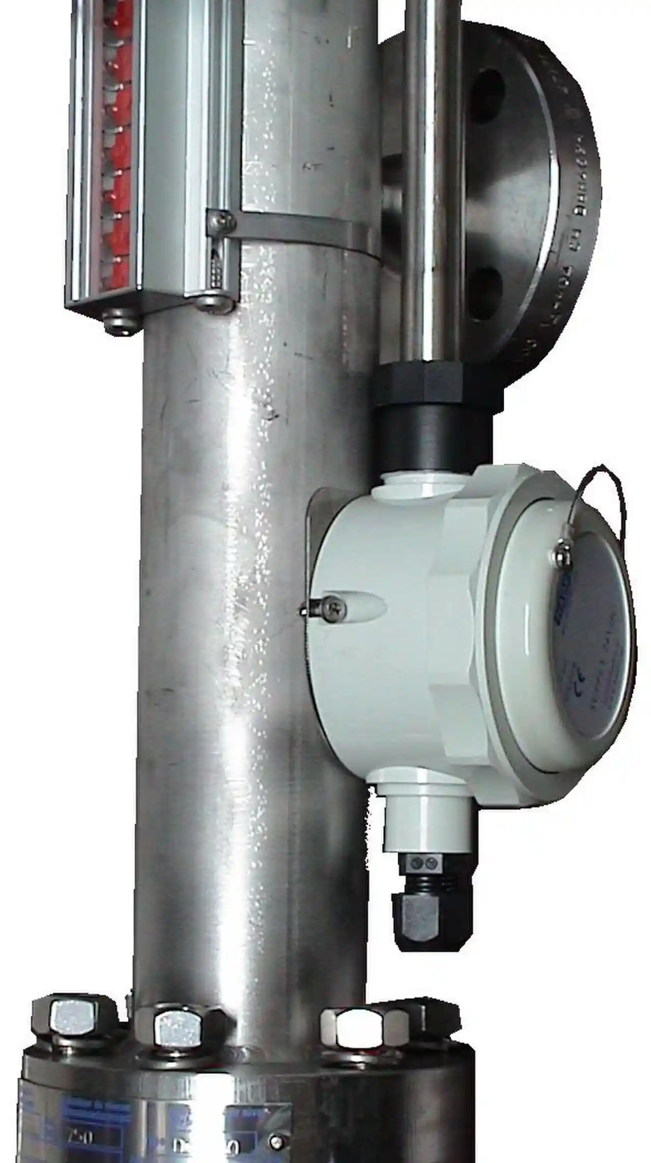
A displacer level transmitter measures continuous liquid level by buoyancy. A sealed cylinder of precisely known volume and weight, the displacer, hangs from a measuring element inside the vessel or in an external cage. As the liquid rises, the cylinder displaces more fluid, the upward buoyant force grows, and the element converts that force change into a signal, classically through a torque tube, a thin walled tube that twists a few degrees and carries the motion out through the pressure boundary. Displacers run 8 to 100 mm in diameter and 300 to 3,600 mm long, and the calibrated span equals the wetted displacer length. The physics is Archimedes' principle at industrial scale, which is why the instrument survives pressures and temperatures that punish newer sensing elements.
Procurement engineers meet displacers on steam drums and boiler level loops, on high pressure separators measuring an oil over water interface, on dehydration and treating vessels, and anywhere a cage mounted instrument with no process diaphragms is preferred. The decision this page settles: cage or internal mount, displacer size against span and density, interface or level calibration, pressure class and materials, and what compensation the density behavior of the fluid demands. The answer lands as an RFQ line set, and every chapter below feeds that line set so the measurement is bought, not hoped for.
This page treats the displacer level transmitter as a purchasing object: how buoyancy converts to torque and signal, what sizing math sets span and interface capability, where cage construction wins and where it plugs, which standards frame boiler and overfill duty, and how torque tube fatigue and buildup show up before failure. It is written for engineers who issue purchase specifications, not for readers who want a brochure summary.
Chapter 1 / 06
What a Displacer Level Transmitter Is and What Is Being Decided
A displacer level transmitter reports where the level is along its span, as a continuous 4 to 20 mA signal proportional to the submerged fraction of a calibrated cylinder. The boundary jobs are easy to state: a continuous band of level belongs to this class of instrument, while a single alarm line belongs to a level switch, and mature practice splits alarm and control functions onto different measurement principles so one fault cannot silence both. On a boiler drum, the displacer or its cage sibling feeds the three element control loop, while independent switches and gauge glasses carry the alarms that boiler code demands. The displacer is bought for the control quality of its signal, not for the paperwork of its alarms.
Its nearest architectural cousins share the same external hardware. A magnetostrictive level transmitter follows a float along a bypass chamber, and a magnetic level gauge hangs a float in a parallel chamber for local indication, as the lead photograph shows. The head based hydrostatic level transmitter reads the same vessel from pressure taps. Top down microwave instruments measure without touching the liquid: a radar level meter in free space, a guided wave radar level probe along a conductor. An ultrasonic level meter serves open atmospheric vessels, and a capacitance level transmitter tracks level along a probe. The full comparison between these families belongs in the selection chapter, and only there; this chapter settles what a displacer is and what its purchase decides.
What is being decided at RFQ stage is a configuration, not a model number. First the service mode: single liquid level, liquid liquid interface, or density and concentration output, because each mode calibrates the same hardware differently. Second the mounting: external cage with its valve set, or cageless internal displacer hung from a single nozzle. Third the sizing: displacer diameter and length against span, liquid density, and, for interface duty, the density difference between the two liquids. Fourth the pressure and temperature envelope, which fixes the cage class and the torque tube architecture. Fifth the compensation: what the transmitter does when density moves with temperature, stated as a requirement rather than left as a hidden error. A quotation that answers all five in writing is a specification instrument; one that answers three is a commodity with a sticker.
Five references organize the datasheet. ASME Boiler and Pressure Vessel Code Section I, paragraph PG-60, governs water level indication and alarms on power boilers and names what hardware must sit on the drum. API 2350 frames overfill management and alarm layering for petroleum storage, the context in which any level transmitter on a tank participates in a safety narrative. Performance figures are evaluated and reported against IEC 60770 practice. Safety function electronics carry IEC 61508 assessment, and wetted parts in sour service follow NACE MR0175, now ISO 15156, material selection. A datasheet quoting none of these is a price tag, not a specification.
Chapter 2 / 06
How Buoyancy Becomes a Measurement Signal
The sensing physics is Archimedes' principle: a body immersed in fluid loses weight equal to the weight of fluid it displaces. A displacer is that body, manufactured so its volume and weight are known to the calibration shop. As level rises from dry to fully wetted, the buoyant force grows in proportion to the submerged volume, and the transmitter reads that force as level. In numbers: a representative displacer 76 mm in diameter and 610 mm long has a volume of about 2.8 liters, so full submersion in water changes the buoyant force by about 27 newtons, 2.8 kilograms force. The force span across the calibrated range equals volume multiplied by the density difference between the liquid and the vapor above it, and every sizing, interface, and error question on this page reduces to that one sentence.
The measuring element in the classic design is the torque tube: a thin walled alloy tube closed at the process end by a cross piece, with the displacer hung on a lever arm. Buoyancy change twists the tube a few degrees, typically 2 to 6, and the tube serves three roles at once: torsion spring, rotary bearing, and pressure boundary feedthrough. On the atmospheric side of the tube, the motion meets either an electronic angle sensor producing 4 to 20 mA, or, in legacy pneumatic builds, a flapper nozzle producing 3 to 15 psi. Range depends on the displacer weight and cross section: a fatter or heavier cylinder produces less angular travel for the same level change, and catalogs pair displacer geometry with tube stiffness to set each span. Order displacers as matched, documented sets, because a lookalike spare cylinder is not a calibration, it is a guess with hardware attached.
Interface duty measures the boundary between two liquid layers. With the displacer spanning both layers, the output follows the interface position only because the two densities differ: the force span across a full interface sweep equals displacer volume multiplied by the density difference between the liquids. Catalogs typically certify interface service down to a density difference of about 0.05 g/cm3, and 0.1 g/cm3 is the practical floor for a loop intended to be trusted, because every force error divides by that difference to become level error. As the two liquids converge in density, the instrument first loses accuracy, then resolution, then meaning, and the honest specification states the expected density difference from samples taken at operating temperature, not from a design basis table.
Density is also the error path, and it moves with temperature. Light hydrocarbons change density by roughly 0.6 to 0.8 kg/m3 per deg C, about 0.1 percent of reading per degree, so an uncompensated transmitter on an outdoor vessel swings 1 to 2 percent of span between night and day. Specify compensation: an integrated sensor, or a temperature from the thermowell by the cage fed to the transmitter or the control system as a density input, with the density versus temperature curve of the actual fluid in the datasheet. Steam drums are the extreme case, because saturated water density falls from about 958 kg/m3 near atmospheric saturation to roughly 735 kg/m3 at 80 bar: a drum transmitter calibrated on cold water compresses the true span by more than 20 percent at pressure, so drum loops carry saturation density compensation keyed to the drum pressure transmitter that every drum already has.
Force measurement earns drift by existing. Torque tube springs creep over thermal cycles, buildup adds weight to the displacer and shifts zero low, and temperature moves both the fluid and the instrument. The consequence is that a displacer installation is bought together with its verification method: equalizing and drain hardware for zero checks, a fill and drain procedure for span, and a scheduled density audit against samples. Chapters 4 and 6 turn those into datasheet rows and maintenance lines. What is being decided on this page is not whether buoyancy works, it does, but whether the bought configuration keeps its numbers between turnarounds.
Chapter 3 / 06
Types, Construction, and Duty Boundaries
The external cage is the classic architecture: a vertical pipe chamber, DN50 or DN80, connected at the top to the vapor space and at the bottom to the liquid, with the displacer hanging inside on its torque tube assembly. Cage isolation valves, a drain, and a vent or equalizing arrangement, classically a three valve manifold, allow isolating, draining, and equalizing the cage for calibration checks without opening the vessel, which is the whole operational argument for the cage. Cages are built as pressure parts, hydrotested and stamped, with ratings from CL150 through CL2500 depending on build; the Fisher 249 family documents the architecture, including cageless variants that suspend the displacer directly in the vessel through a single nozzle, trading calibration access for fewer penetrations.
The cageless internal mount hangs the displacer on a flanged head through one top nozzle. It is chosen when nozzle real estate is scarce, when the service is fouling enough that a cage would slowly fill with solids and stop following the vessel, or when the vessel code makes a second penetration expensive. Its price is literal: any calibration or inspection work beyond an electrical zero check means a vessel entry or an isolation and blinding permit. Interface service and drum level service almost always pay for the cage, because those loops earn their keep through verification, and a measurement that cannot be checked between turnarounds quietly stops being trusted.
Materials follow the chemistry. 316L displacers and torque tubes are the catalog default and cover hydrocarbons, steam condensate, and most chemicals. Alloy 400 buys resistance in brine and seawater duty. Alloy C-276 serves sour and chloride acid service and is the standard answer when ISO 15156 governs material selection. Carbon steel cages with stainless internals keep oil service economical. Steam duty brings insulated cages, extended or air cooled torque tube housings, and elastomer free architecture at the hot end, all of which exist to keep the electronics within their rating while the process sits at saturation temperature.
The envelope is wide, which is the point of the technology. Process temperatures of minus 30 to 200 deg C cover standard builds, and steam duty variants with extended torque tube architecture work toward 340 deg C. Pressure ratings follow the cage hardware: CL2500 cages hold over 400 bar at ambient temperature, derating with heat exactly as the flange standards table. No other continuous level principle offers moving metal parts proven at that combination of pressure, temperature, and interface capability, and the limits that remain are mechanical, not electronic: span length, density difference, and fouling.
The boundaries deserve blunt statements. A displacer measures density weighted level, so any density change reads as a level change unless compensated. A cage in solids laden service plugs at the lower connection and then reports the cage, not the vessel. An interface span with 0.05 g/cm3 difference is a certificate, not a control loop. A 3,600 mm displacer is a pendulum: install it plumb or it touches the cage wall and turns every level reading into a friction reading. The table below maps common duties to the construction that survives them.
Service
Construction to specify
Construction to avoid
Power boiler drum level, 70 to 120 bar
Welded cage, saturation density compensation, code compliant hardware per PG-60
Cold water calibration left uncompensated at pressure
High pressure separator interface, CL600
CL600 cage, 316L, interface calibration with live samples
Catalog density difference assumed for the pair of liquids
Insulated or heat traced cage, temperature compensation
Bare cage exposed to ambient swings
LPG storage vessel level
Cage with vapor equalization and roddable connections
Undersized lower connection that vapor locks at startup
Fouling sludge service
Cageless internal displacer with turnaround access
Narrow annulus cage without flushing arrangements
Chapter 4 / 06
Key Specification Parameters
The rows below decide whether a quoted instrument matches the service; the paragraphs after the tables say what a complete datasheet states and what a weak one hides.
Attribute
Typical range or options
What it decides
Displacer diameter
8 to 100 mm
Buoyant force per unit level and cage bore requirement
Displacer length
300 to 3,600 mm
Calibrated span equals wetted displacer length
Force span, reference example
76 mm by 610 mm displacer, about 27 N in water
The signal budget all errors divide into
Calibration density range
about 0.4 to 1.5 g/cm3 in standard catalogs
Which liquids the span can be certified against
Interface minimum density difference
0.05 g/cm3 certified floor, 0.1 g/cm3 recommended
Interface accuracy and whether the loop is trustworthy
Cage class
CL150 to CL2500, DN50 or DN80 connections, RF or RTJ
Pressure boundary rating with standard temperature derate
Process temperature
minus 30 to 200 deg C standard; toward 340 in steam builds
Torque tube architecture and electronics housing style
Materials
316L, Alloy 400, Alloy C-276, carbon steel cage
Corrosion envelope and ISO 15156 compliance where sour
Output
4 to 20 mA with HART; 3 to 15 psi pneumatic legacy
Control system interface and diagnostics availability
Accuracy and repeatability
plus or minus 0.5 to 1.5 percent of span; about 0.25 percent repeatability
Expectations quoted against actual process density
Valves and manifold
Cage block, equalize, and drain set, full port
Whether zero and span can be checked in service
Several rows deserve prose. Span: state it in buoyancy terms, volume times density difference, not only in millimeters, because the force budget is what error divides into, and a 0.05 g/cm3 interface span has a force budget one tenth of a water level span on the same cylinder. Materials: demand the material certificates and, in sour service, the ISO 15156 compliance statement for every wetted part including the torque tube. Valves: the equalize and drain set is not an accessory, it is the calibration interface, and full port geometry is what keeps the cage following the vessel. Accuracy: the quotation must state reference conditions, fluid, density, and temperature, or the percentage is marketing.
The service mode table compresses the calibration decision for specification meetings.
Service mode
Calibration basis
Sizing driver
In service verification
Single liquid level
Calibrated at operating density of the liquid
Span against displacer length
Equalize and fill two point check
Interface between two liquids
Calibrated with both process liquids
Density difference sets the force span
Sampled interface test at turnaround
Density or concentration output
Calibrated on a density scale at fixed immersion
Volume and tube sensitivity
Lab density sample against reading
Drum level on saturation duty
Cold calibration plus saturation compensation curve
Cage length against band of interest
Cross check against gauge glass and probes
Temperature compensation deserves its own datasheet line, because it is the difference between a reading and a fact. The compensation needs a temperature representative of the liquid in the cage, so the thermowell belongs adjacent to the lower cage connection, not on a distant line where steam tracing or sunlight lies to the calculation. Where the transmitter accepts an external temperature input, state the source; where it computes internally, state the sensor location and its calibration. A weak quotation on this line is a single phrase, temperature compensated, with no curve, no source, and no stated residual error, and it should be sent back.
Chapter 5 / 06
Selection Decision Factors and RFQ Language
The decision sequence is short enough to run as a checklist in a specification meeting, and each step eliminates a class of quotations before price comparisons begin.
Fix the service mode: level, interface, or density output, because everything downstream calibrates against this choice.
Write the fluids as they are, with densities at operating temperature from samples, not from the design basis datasheet inherited from another project.
For interface duty, compute the density difference honestly and reject the application if it sits near 0.05 g/cm3 and the loop matters.
Choose cage or cageless on verification needs: cages buy in service checks at the price of two nozzles and freeze protection.
Size the displacer so the span of interest covers 60 to 90 percent of its length, keeping signal budget away from both mechanical ends.
Set the pressure and temperature envelope, then pick cage class, torque tube architecture, and materials with certificates.
Specify density compensation explicitly: curve, source, and residual error, with the thermowell location named.
Fix the verification regime: equalize check interval, fill and drain span check at turnaround, and proof test path for any safety function.
Measured against the modern families, honestly and only here in the selection chapter: a guided wave radar level probe has no moving parts, needs no density assumption, and installs on a single top nozzle; its weaknesses are heavy coating on the probe, emulsion layers that scatter the pulse, and the mechanical realities of long probes in tall cages. A radar level meter is non-contact and is the default new build choice for clean vapor spaces; foam, tall narrow nozzles, and heavy vapor can still defeat the reflection. The hydrostatic level transmitter is the historical rival at the same vessel: built on a differential pressure transmitter, simple and proven, but density dependent by the same physics as the displacer, and in hot service it drags impulse lines or a diaphragm seal whose fill fluid limits temperature and shifts zero with ambient; fitted with a diaphragm seal on both taps it climbs in cost until the comparison resets. An ultrasonic level meter works only on open, atmospheric vessels and shares vapor sensitivity. A capacitance level transmitter fights buildup on its probe. A magnetostrictive level transmitter in a bypass cage delivers millimeter class accuracy in clean liquids but needs a clean float path. The displacer keeps four defensible grounds: interface duty with a real density difference, density and concentration as a native output, pressure and temperature ratings proven at CL2500 separator and drum service, and retrofit into the enormous installed base of cages, where a modern electronic head upgrades the loop without a single new nozzle.
Two purchase patterns follow from that comparison. Retrofit: many drums and separators already carry cages and torque tube hardware, and replacing the head while keeping the documented displacer is the cheapest defensible modernization on site, provided the original displacer volume and weight records still exist; order the records search before the RFQ. Interface: where the density difference is real, 0.1 g/cm3 and up, the displacer measures the boundary directly and predictably, while a probe reading the upper layer needs an inference and a tank gauging approach needs stillness. Where the vessel already carries a differential pressure transmitter on the lower taps, compare quotes on total cost of verification and drift between turnarounds, not on tag price.
The application map turns the reasoning into a table the project file can carry.
Application
Construction to specify
Check before order
Power boiler drum level
Welded cage, saturation density compensation, code hardware
Compensation source: drum pressure transmitter tag; required gauges and alarms in the same package
High pressure separator interface
CL600 cage, 316L, interface calibration from live samples
Sampled density difference at operating temperature
Insulated or traced cage, temperature compensation
Ambient swing effect on span; compensation curve in quotation
LPG storage level
CL300 cage, vapor equalized, roddable connections
Vapor lock behavior at startup and cooldown
Retrofit of an existing cage installation
Electronic head matched to the existing displacer and cage
Displacer volume and weight records; matched calibration data
The RFQ block should be written once and reused. A complete block reads: quantity and service mode; span with the band of interest marked; fluids with densities at operating temperature, from samples, and density difference for interface duty; mounting, cage or cageless, with connection size, class, and facing; displacer diameter, length, and material; cage material and rating with hydrotest certificate; torque tube architecture and rating; output with fail behavior and HART where used; accuracy statement against the actual fluids with reference conditions; density compensation curve, temperature source, and residual error; valve and manifold arrangement; material certificates, ISO 15156 statement where sour; and acceptance as a wet calibration witnessed at FAT with the documentation of the displacer set, volume, weight, and matched calibration constants. A quotation returned without the span in buoyancy terms, the reference conditions, or the compensation curve is incomplete at any price.
Chapter 6 / 06
Installation, Standards, Failure Modes, and Maintenance
Installation quality decides whether the cage reads the vessel or reads itself. Set the cage plumb within about 2 degrees, because a 3,600 mm displacer swinging even 10 mm sideways touches the wall and adds friction to the measurement. Align both cage connections to true vessel elevations, upper in the vapor space, lower in the liquid band, with full bore piping and no pockets where gas can collect on the liquid leg; a vapor locked lower connection freezes the reading mid range while the vessel drains underneath it. Thermal growth between the two nozzles must go somewhere: support the cage on one nozzle and let the piping flex, or the vessel teaches the cage its stress. Heat trace and insulate water and condensate service, ground and bond the loop properly, and orient the torque tube housing so its electrical head stays out of the weather and the drip path.
Commissioning proves the loop with liquid. Fill the cage through the vent in measured steps and record output versus fill height in percent of span, the two point check that catches a transposed range constant or a damaged displacer before the plant hands over. Verify the zero with the equalizing arrangement, confirm the fail behavior of the electronics by breaking the loop, and cross check the installed reading against the gauge glass or magnetic level gauge on the same vessel. Document the reference densities used, because every later argument about drift resolves against that piece of paper.
The standards set the verification frame. ASME Section I paragraph PG-60 governs drum level indication and alarms on power boilers, including what hardware the code requires beside the transmitter. API 2350 frames overfill management for storage, the layer of protection context in which any tank level instrument participates. IEC 60770 practice underlies comparable performance data, IEC 61508 assessment covers any output feeding a safety function, ISO 15156, formerly NACE MR0175, governs materials in sour service, and the pressure boundary carries PED conformity where the plant sits under it. Citing these by name in the RFQ moves the burden of proof to the supplier, which is where it belongs.
Failure modes follow a short and litigious list. Torque tube fatigue is the classic: years of thermal and pressure cycling end in a broken tube, a pinned or wildly unstable signal, and an unplanned unit trip, and the warning sign is span drift between annual checks, which is why span trend records exist. Displacer buildup adds weight and shifts zero low, the signature in produced water and heavy oil, and it is caught by weighing the displacer against its record card at turnaround. A plugged lower connection freezes the cage, the separator complaint, and the countermeasures are flushing, heat tracing, and roddable connections. A pinhole in a welded displacer slowly fills with process liquid, the buoyant force collapses, and the reading walks to permanent low; the fix is inspection and a matched spare. Vapor lock, freezing of unprotected legs, and mechanical overrange from slugs complete the list. Every one of these modes announces itself early in the zero and span record, which is the entire argument for keeping one.
Maintenance is verification on a schedule. Annually: equalize zero check with the record signed, span trend reviewed against previous years, and the compensation temperature source audited. Each turnaround: pull the displacer, weigh it against its record, inspect the torque tube and bearings, clean the cage, and recalibrate with a witnessed fill test; sample the process liquid for a density audit read together with the cage thermowell. Keep the matched spare displacer and its calibration constants in stores, because the matched set is the calibration. Where the transmitter feeds a safety narrative, proof test the alarm path through an independent level switch and record the cross check. A displacer installation that keeps its numbers between turnarounds was bought with its verification method attached, and one that does not was bought on price.
FAQ
What density difference is needed for interface measurement?
Interface duty needs a density difference between the two liquids of at least about 0.05 g/cm3, and 0.1 g/cm3 is the practical minimum for a loop you intend to trust, because the force span equals displacer volume multiplied by that difference. As the difference shrinks, the same force error becomes a larger level error, so accuracy must be quoted against the actual process fluids and not against water.
Why does the reading drift with temperature?
The measurement is buoyancy, and buoyancy follows density. Light hydrocarbon density changes by roughly 0.6 to 0.8 kg/m3 per deg C, so a 20 deg C swing shifts the reading by one to two percent, uncompensated. Specify a transmitter with temperature compensation, feed it from the thermowell near the cage, or accept and document the error. Steam drums carry saturation density compensation for the same reason.
Are displacers still the right choice on steam drums and high pressure vessels?
On steam drums and high pressure separators the displacer remains a defensible choice because the external cage isolates the wetted parts without impulse lines or fill fluids, and rated cages reach ASME CL2500. The cost is moving parts: torque tube fatigue and displacer buildup are real failure modes with known signatures. Many new boilers now carry an independent top mounted probe as primary with the displacer kept for cross checking, a decision the selection chapter covers.
How do I verify calibration without taking the vessel offline?
Use the cage valves. Closing the upper and lower isolations and equalizing the cage puts the displacer in a known dry state for a zero check, and a controlled fill through the vent gives the 100 percent point against a measured fill height. Record output versus fill in percent of span. Interface verification needs the actual process liquids, so schedule full calibration at turnaround and rely on cross checks between shutdowns.
What kills displacer transmitters in service?
Three failure modes dominate. Torque tube fatigue ends in a sudden wild or pinned reading after years of cycling, and shows earlier as span shift between annual checks. Buildup on the displacer adds weight and shifts zero low, typical in produced water and heavy oil. Solids in the cage plug the lower connection, the cage stops following the vessel, and the reading freezes; heat tracing, flushing, and roddable connections are the countermeasures.
Cage mount or internal displacer mount?
External cage mounting isolates the instrument for maintenance, allows in service calibration checks through its valve set, and suits the classic two or three valve manifold arrangement; its cost is a pair of nozzles plus possible freeze protection. Internal mounting puts the displacer directly in the process and avoids cage plugging, but any work means a vessel entry. Interface and drum level service almost always use the cage.
What accuracy should I demand on a quotation?
A fair expectation is plus or minus one percent of span or better on clean liquid level, quoted against the actual process density, with repeatability near 0.25 percent. Interface accuracy degrades with the density difference as chapter 2 explains. Insist that the quotation states reference conditions, span in buoyancy terms, and behavior at the density extremes, because a bare percentage without conditions cannot be checked and belongs in the reject pile.