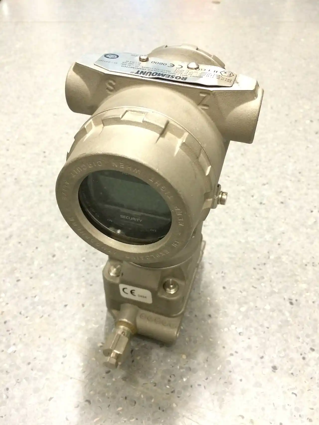
A hydrostatic level transmitter infers liquid level from the pressure that the liquid column exerts at a measuring point: pressure equals density times gravity times height, so a fixed-depth sensor reading a clean, constant-density liquid reports height directly. The sensing element is a piezoresistive pressure cell, the same instrument family as a pressure transmitter, packaged for the duty in one of three forms: a submersible probe dropped to the bottom of the tank on its cable, a flanged or threaded transmitter mounted at a nozzle, or a differential pressure transmitter spanning the vapor and liquid sides of a pressurized vessel. For water, one meter of depth is 9.81 kilopascals, about 1.42 psi, and every other liquid scales that number by its specific gravity.
The method's honesty is its weakness: it measures pressure and trusts the buyer to manage density. It is the cheapest reliable continuous level technology on open tanks and wet wells, it ignores foam and vapor above the liquid that blind an ultrasonic level meter, and it has no moving parts in the tank. It must not be sold as a mass or interface instrument, it drifts when density drifts, and on pressurized vessels it needs a differential installation with all the leg and seal engineering that brings. This page works the three installation forms, the density and venting arithmetic that decides accuracy, the boundary against radar and guided-wave alternatives, and the RFQ lines that pin range, accuracy, and materials.
This page treats the hydrostatic level transmitter as a pressure instrument with a level job: head-to-height arithmetic with density correction, submersible versus flanged and DP installation forms, vent-tube and seal engineering, the honest boundaries against radar and guided-wave measurement, and the RFQ lines that make a probe fit its tank rather than merely its budget.
Chapter 1 / 06
What a Hydrostatic Level Transmitter Is and What Is Being Decided
Level measurement families divide by what they actually sense, and hydrostatic is the pressure family. A radar level meter times an electromagnetic echo off the liquid surface; an ultrasonic level meter times a sound echo; a guided wave radar level device reads a pulse along a probe; a float rides the surface; capacitance and conductance probes read dielectric and electrical contact. The hydrostatic instrument ignores the surface entirely and weighs the column: put a pressure sensor at the bottom, let the liquid push, and the height follows from the pressure once the density is known. That is why the method is blind to foam, mist, vapor, agitation at the surface, and tank internals above the sensor, which defeat echo methods, and why it is simultaneously hostage to density, which echo methods never see.
What is being decided is the installation form and the accuracy budget that comes with it. Open tank or wet well with the sensor near the liquid: the submersible probe, two-wire 4 to 20 mA, dropped on a vented cable, is the default and the cheapest reliable continuous reading in industry. Vessel with a nozzle at the bottom or side: a flanged transmitter, optionally with a flush diaphragm seal for viscous or crystallizing product, mounts like any pressure instrument. Pressurized vessel, boiler drum, or tank with blanket gas: the vapor pressure no longer cancels, and a differential pressure transmitter with a low-side leg, dry, wet, or sealed, measures the difference that the liquid column alone causes. Each form carries its own error terms, vent-tube moisture for the probe, seal fill temperature effects for the flanged, leg condensation for the dry-leg DP, and the buyer is really choosing which error terms the site can discipline.
The second decision is scope honesty: what accuracy the process needs and what density behavior the liquid has. A wet well controlling a submersible pump needs repeatability more than absolute truth; a custody-adjacent tank reading wants density compensation by temperature or a better technology; an interface between two liquids is not a hydrostatic duty at all unless the two densities are stable and different by a known margin, in which case a pressure difference across a known gap reads the interface position. The method's purchase price advantage is real and large, and the honest selection spends a paragraph making sure the cheap instrument is not being asked a question it cannot answer.
Positioning inside the plant's instrument list is straightforward. The generic level transmitter family page maps the technology landscape; hydrostatic is the pressure-based member of that family. Adjacent instruments share the loop: the same tank usually carries a pressure transmitter on the vapor space where one exists, a thermowell with a temperature measurement feeding density compensation, and, where flow matters, a flow meter on the inlet or outlet whose totalizer the level reading cross-checks by mass balance. Hydrostatic level is one citizen of that small economy, and its RFQ is written knowing the neighbors.
Chapter 2 / 06
Head Physics, Density, and Venting Arithmetic
The core equation is exact: pressure equals density times gravitational acceleration times height. For water at 4 deg C, one meter of column produces 9.81 kilopascals, 98.1 millibar, about 1.42 psi, and catalog ranges quote directly in meters of water column, 2.5, 5, 10, 20, 50, 100 m as the standard ladder, with deep-well probes beyond. A liquid of 0.8 specific gravity produces 80 percent of the water figure, one of 1.2 produces 120 percent, and the arithmetic runs both ways: the instrument reports pressure, the display applies a range constant, and if the constant's density assumption is wrong by five percent, the level reading is wrong by five percent, silently, forever.
Density moves with temperature, composition, entrained gas, and suspended solids. Water's density changes about 0.02 to 0.04 percent per kelvin around ambient, so a 30 kelvin day-night swing in an outdoor tank is a one percent reading drift unless compensated; hot oil and process liquids move several times more, and temperature compensation via a separate measurement in a known thermowell location is the standard correction. Entrained air is the dishonest one: aerated liquid has an apparent density anywhere below the true value, and a hydrostatic probe in an aerated sump reads low in proportion to the gas fraction, the classic failure on agitated and pumped tanks. Suspended solids do the reverse, adding apparent density as concentration rises. The engineering summary: hydrostatic accuracy is a density-knowledge statement, and every percent of density uncertainty is a percent of level uncertainty.
Venting is the second arithmetic. A submersible probe measures gauge pressure: the cell's low side must reference atmosphere, and it does so through a capillary tube running the length of the cable, open at a junction box above any flood level. That vent is the installation's most failure-prone component: moisture in the tube changes the reference pressure by millibars, which on a 2.5 meter probe is a percent-scale error, and every maintenance program for vented probes includes desiccant and tube checks. On pressurized vessels the reference is the vapor space itself: the differential pressure transmitter reads high side minus low side, and the liquid column is the only difference between them. Dry-leg installations keep the low side gas-only; wet-leg installations deliberately fill the low side with a constant reference liquid; sealed systems cap both sides with diaphragm seals and capillaries when the vapor condenses, plugs, or corrodes. Each leg design carries known corrections, leg height and fill density, which belong in the calibration sheet, not in folklore.
Sensor physics sets the floor performance. Piezoresistive silicon cells deliver typical accuracy 0.1 to 0.25 percent of calibrated span, long-term stability around 0.1 to 0.2 percent per year class, and overpressure survivability of 2 to 3 times range, which matters because a probe dropped into an empty sump at pump-out sees vacuum and surge transients rather than clean hydrostatics. Temperature effects on the cell itself, zero and span drift per kelvin, are compensated digitally in current-generation transmitters and belong on the datasheet as a total effect figure at the installed temperature band. Response is fast, milliseconds class, limited in practice by the hydraulic path: long capillaries on sealed DP systems add the same seconds-scale lag that any sealed pressure loop carries, which matters only when the level loop is tight control rather than monitoring.
The last piece of arithmetic is zero elevation. The measuring point sits at the tank bottom or nozzle, the display wants zero at the tank's reference line, and the offset between them, plus any wet-leg correction, is a zero-shift constant entered at commissioning. The discipline is to write the constant on the calibration record with the tank drawing reference, because in five years the only question anyone will ask is why the display reads 0.4 meters with the tank visibly empty, and the answer lives in that constant.
Chapter 3 / 06
Installation Forms, Materials, and Duty Boundaries
The submersible probe is the family's workhorse form: a cylindrical 316L or higher-alloy body, typically 20 to 30 mm diameter, with the pressure port at the nose, a piezoresistive cell inside, and a molded cable carrying signal pair plus vent tube, polyurethane or FPE jacket by chemistry, weighted or secured at the tank bottom. Ranges from 2.5 to beyond 300 meters of water cover sumps to deep wells. The form's virtues are price and blind simplicity: no nozzle needed, install by lowering, read by 4 to 20 mA into any input card. Its disciplines are the vent tube's dryness, protection of the cable in the tank, and placement away from pump suction turbulence, because a probe in the inflow plume or beside a running submersible pump reads every hydraulic disturbance in the well.
The flanged or threaded transmitter mounts at a nozzle and reads the column from the vessel wall. On clean liquids it is simply a gauge pressure transmitter with a range in meters of water; on viscous, coating, or crystallizing product, a flush diaphragm seal keeps the product out of the impulse path, with the seal engineering, fill fluid, capillary, thermal effects, carried over from that discipline. Side-mounted readings sit above the bottom, so the zero elevation constant accounts for the height of the nozzle, and the drain-and-vent behavior of the nozzle becomes part of the maintenance round. This form prices above the probe, but serves where nothing may hang into the tank, where agitators make probe cables impossible, or where sanitary and code flanges are the norm.
The differential installation serves pressurized vessels, and its engineering is the leg design. Dry legs suit clean, non-condensing vapor; wet legs suit condensing steam and hot vapor, with a constant reference fill whose density is in the calibration sheet; sealed legs with diaphragm seals and capillaries serve corrosive, plugging, or freezing service and import the seal family's temperature-error behavior. The differential pressure transmitter itself is the standard process instrument, spanned in the column's pressure difference, with the vessel's design pressure as static rating. Boiler drums, blanket-gas tanks, and pressurized chemical storage are the home duties, and on all of them the level reading is only as honest as the leg symmetry, which is why Chapter 6 returns to leg insulation and equal-length capillaries.
Form
Typical range
Best duty
Hard boundary
Submersible probe
2.5 to 300 m water
Open tanks, wet wells, boreholes
Pressurized vapor space; density uncertainty; agitation plumes
Flanged gauge transmitter
2 to 200 m water by span
Vessel nozzles, clean liquids
Coating and crystallizing product without a flush seal
Flush-seal flanged
by cell plus seal span
Viscous, coating, hygienic duties
Seal fill thermal error on tight spans
DP transmitter with legs
0.25 to 30 m column typical
Pressurized vessels, boiler drums
Leg condensation and asymmetry; freezing legs
Materials ladder by wetted chemistry exactly as pressure instruments: 316L is the default for water and wastewater, alloys 276 and titanium for aggressive chemistry, PVC and PP probe bodies and cables exist for galvanic and chemical economies, and gold or tantalum facings appear only where the chemistry bill demands. Cable jacket chemistry matters as much as body metallurgy, polyurethane for general duty, FPE and FKM jackets for hydrocarbon and chemical exposure, and the vent tube terminations stay dry by desiccant or by a hydrophobic membrane breather on the junction box.
Duty boundaries, sentence by sentence. Surface with heavy foam, vapor, or condensation where echo methods struggle: hydrostatic wins by ignoring the surface. Interface between two liquids: only when both densities are stable and known, and a pressure-difference pair is the honest instrument; otherwise guided wave radar level measurement owns the interface duty. Deep well or borehole: the probe is the standard. Tank with agitator: flanged, not probe, because cables fatigue. Pressurized with condensing vapor: wet-leg or sealed DP, never a gauge probe, because the vapor pressure is not the level. Granular solids and powders: not a hydrostatic duty at all, the column mechanics do not hold, and rope or weight sensors own the silo. And high-accuracy inventory or custody transfer: density-compensated hydrostatic can serve, but the honest comparison at that accuracy class is a mass or radar inventory system.
Chapter 4 / 06
Key Specification Parameters
The decode table carries the rows that decide fit and the rows vendors quietly default when the RFQ leaves them blank.
Parameter
Typical catalog spread
What it decides
Range in meters of water
2.5 to 300 m probe; 0.25 to 30 m DP column
Span choice with margin, not padding, at tank truth
0 to 50 deg C probe class; compensated band stated
Cell error and density compensation basis
Vent reference
vented cable tube plus desiccant or breather
The gauge reference integrity on probe forms
Ingress and submersion
IP68 to stated depth; junction box IP66 or better
Flood and washdown survival of the whole loop
Approvals
ATEX or IECEx, drinking water, marine as needed
Legal install in the jurisdiction and service
Long-term stability
0.1 to 0.2 percent per year class
Calibration interval economics
Range selection is a calibration decision more than a hardware one. Order the range to the tank's true working band plus transient margin: a 5 meter probe in a tank that works between 0.3 and 3.5 meters spends most of its life on 60 percent of span, which is fine, while a 50 meter probe in the same tank throws away a digit of usable resolution for no duty reason. On DP columns, range is the pressure difference at maximum level, corrected for leg constants, and the zero elevation constant belongs on the same calibration sheet.
The density row is implicit and belongs in the RFQ as a stated assumption: nominal specific gravity, expected variation band, and the compensation method if any. A vendor quoting 0.1 percent accuracy on a liquid whose density varies 3 percent is quoting an instrument the process will out-drift, and the discrepancy belongs to the selection meeting, not the warranty file. Where temperature drives the variation, a temperature input from the tank's existing thermowell and a two-point density model in the display recover most of the error for negligible cost.
The vent row applies to probe forms and decides their maintenance economics: vented cable, desiccant cartridge or membrane breather at the junction box, flood-proof termination height. On sealed and leg forms, the analogous rows are fill fluid and capillary length and the leg constant, and both sets of rows should be filled with the same seriousness, because they are where field drift is born. Approvals close the table: hazardous area marking for sumps in classified zones, drinking-water contact certificates for potable service, and marine type approval where the tank is on a ship, each a line item that stops delivery when missing.
Chapter 5 / 06
Selection Decision Factors and RFQ Language
The selection sequence starts with the tank, because the tank decides the form before any catalog opens.
State the vessel: open or pressurized, blanket gas or not, agitator or not, nozzle availability, access for service. This fixes probe versus flanged versus DP form.
State the liquid: chemistry, nominal and varying specific gravity, temperature band, solids or entrained gas, coating behavior. This fixes materials, seal needs, and whether hydrostatic is honest at all.
State the level band and accuracy need: working range, dead bands at top and bottom, control versus indication duty. This fixes span and the accuracy class worth paying for.
State the density truth plan: constant assumption, temperature compensation, or cross-check by mass balance with the site flow meter inventory. This converts the technology's weakness into a managed number.
State the environment: flood level, washdown, freeze risk, classified area. This fixes ingress class, breather strategy, heat tracing of legs, and approvals.
Select accessories by the above: weighted nose or stilling pipe, desiccant kit, junction box, lightning surge protection on long outdoor runs, calibration at two points.
Write the RFQ with every Chapter 4 row filled, the density assumption stated, and the calibration points named.
Cost behavior is the technology's headline. As a planning spread: a submersible probe with cable sits at the bottom of the continuous-level price ladder; a flanged transmitter runs 2 to 4 times the probe by class and alloy; flush-seal forms add the seal premium, 1.5 to 3 times the bare flanged; a DP installation with legs and hardware prices as a process loop, commonly 3 to 6 times the probe. Against echo technologies, a radar level meter of 80 GHz class runs several times the probe price and buys immunity to density and vapor issues it does not have; an ultrasonic level meter prices between probe and radar and buys non-contact at the cost of foam and vapor blindness. The comparison table holds the real trades.
Option pair
Relative cost
What you gain
What you pay in
Submersible probe vs flanged transmitter
1.0 vs 2 to 4
Nozzle mount, service access, agitator safety
Price, installation steel
Probe vs ultrasonic level meter
1.0 vs 1.5 to 3
Non-contact, no wetted parts
Foam and vapor blindness, beam space
Probe vs radar level meter
1.0 vs 4 to 8
Density and vapor immunity, tight accuracy
Price, dielectric limits at the low end
Gauge flanged vs sealed DP with legs
1.0 vs 1.5 to 2.5
Pressurized-vessel correctness
Leg engineering, condensation discipline
Bare vs drinking-water certified probe
1.0 vs 1.1 to 1.3
Legal potable install
Paperwork, material restrictions
The RFQ checklist writes out as: vessel form and pressure state; liquid chemistry with specific gravity band; working level range with dead bands; required accuracy at stated density assumptions; range in meters of water and the calibration points; output, supply, and cable length; wetted materials body, diaphragm, and cable jacket; vent strategy with breather or desiccant kit; ingress and submersion class; approvals by jurisdiction; accessories, stilling pipe, weighting, junction box, surge protection, named in the order; and the long-term stability figure with the calibration interval it implies. Quotes answering every row are comparable; quotes answering most rows are cheaper for reasons the missing rows explain.
The neighboring instruments close the loop economy. The vapor-space pressure transmitter on a blanketed tank, the temperature measurement in its thermowell feeding density compensation, the pump control that the wet-well probe feeds: each shares the loop or the vessel, and the level instrument that reads consistently with their trends is the one that stays trusted. The hydrostatic choice is correct when the plant wants continuous level at the lowest installed cost and is willing to own density as a managed assumption, and the RFQ above is the document that makes that ownership explicit.
Chapter 6 / 06
Installation, Standards, Failure Modes, and Maintenance
Probe installation is placement discipline. Keep the probe out of the inflow plume and away from the suction of the duty pump; a stilling pipe or a quiet corner converts a noisy reading into a usable one at the cost of a piece of pipe. Do not let the probe rest on moving sludge; suspend it a hand's width above the floor or mount it in a short still well. Protect the cable in the tank, conduit for the run above the flood line, secure termination where nothing tugs it, and terminate the vent in a junction box fitted with desiccant or a hydrophobic breather, mounted above any conceivable flood, because a drowned vent is the number one field failure of the form. Record the zero elevation constant and the mounting depth on the calibration sheet at commissioning.
Flanged and DP installations carry the pressure-instrument disciplines. Flange face and gasket suit the service class; impulse piping stays short, sloped, and heat-traced where freeze threatens; wet legs are filled with the documented reference fluid and their constant written into the calibration; capillary pairs on sealed systems run equal length on the same side of the vessel so ambient temperature hits both legs together. On steam and hot service, the condensate pot is part of the instrument, not piping optimism, and the drum-level DP loop gets its own commissioning procedure because its errors are the plant's oldest story.
Commissioning is a two-point calibration against physical truth: empty and one known level, or two known levels, read into the transmitter or display, with the density assumption and leg constants applied and recorded. The cross-checks are free: a manual dip or sight glass at two levels, and a mass-balance test against the site's flow meter totals over a fill or drain cycle, which catches density errors and leg faults in one exercise. File the sheet with the constants; every future drift investigation starts there.
The standards frame is the pressure-instrument frame: performance and test basis by the process transmitter standards families, EN 61298 and IEC 60770 class terminology for accuracy statements; hazardous-area installation by ATEX or IECEx marking and the plant's area classification; drinking-water contact by the jurisdiction's potable certificates; marine duty by classification-society type approval; and SIL capability statements under IEC 61508 where the level loop feeds a safety function, with the probe's declared capability and the loop's proven-in-use record as separate documents. Citing the applicable ones in the RFQ is how the delivered unit arrives with the right paperwork rather than a generic conformity leaflet.
Failure modes rank with field history. Vent moisture leads on probe forms, presenting as slow drift or weather-correlated error; the cure is desiccant renewal and breather integrity, and the detection is a zero check against an empty sump. Diaphragm and port fouling follows on coating duties, a scaled or waxed nose reads a plausible wrong number, and the cure is cleaning access specified at purchase, a flush port or retrieval design. Leg faults own the DP family: condensation in a dry leg, a frozen leg, a lost wet-leg fill, each presenting as a step or a slow offset, each prevented by the insulation and tracing reviewed at installation. Cell damage by overpressure or vacuum transients, pump-out slams and water hammer, appears as shifted zero that no recalibration holds, and the protection is a surge-tolerant range choice and check-valve discipline on the hydraulic path. Electronics and cable damage, moisture ingress at terminations, rodent and abrasion cable faults, close the list, prevented by the junction box and conduit practice that costs little and is documented everywhere.
Maintenance is therefore short and scheduled: desiccant or breather service on the probe vent round, quarterly class; a two-point verification annually or at the stability interval the datasheet states, adjusted only when the physical check disagrees; leg and capillary inspection with the winter readiness round on DP systems; and a cleaning schedule on coating duties matched to the product's fouling pace. The instrument's promise is a decade of unattended accuracy if the vent stays dry, the density assumption stays honest, and the calibration sheet stays findable, and the entire maintenance program is those three sentences with dates attached.
FAQ
How accurate is a hydrostatic level reading really?
The cell holds 0.1 to 0.25 percent of span; the reading holds only as well as your density knowledge. Every percent of specific-gravity uncertainty is a percent of level error, and temperature swings of 30 kelvin in an outdoor water tank alone move density about one percent. Budget cell plus density plus vent effects together, and the honest number for a plain probe install is closer to 1 percent than to the datasheet.
Why does my submersible probe drift when it rains?
Moisture in the vent tube. The probe measures gauge pressure referenced to atmosphere through a capillary in its cable; water in that tube offsets the reference by millibars, which on a short-range probe is percent-scale. Desiccant renewal, a hydrophobic breather, and a termination box above flood level are the cure.
Can I use a gauge probe on a tank with blanket gas pressure?
No. The probe would read liquid head plus blanket pressure as if it were level. Pressurized vessels need a differential measurement, a DP transmitter with a low-side leg to the vapor space, so the vapor pressure cancels and only the column remains.
How do I compensate for density changes with temperature?
Add a temperature measurement, usually from an existing thermowell in the tank, and apply a two-point density model in the display or controller: level equals pressure divided by density at temperature. It recovers most of the thermal error for the cost of one input card channel and a lookup table.
When should I pay for radar instead?
When density is unstable or unknown, when the vapor space is condensing or pressurized in ways legs cannot discipline, or when inventory accuracy demands better than the density uncertainty. An 80 GHz radar level meter is several times the probe price and buys freedom from the one variable the probe cannot see through.
Does foam or agitation affect the reading?
Surface foam does not, which is a hydrostatic strength. But turbulence and entrained air do: an aerated plume lowers apparent density and the reading with it, and a probe beside a pump inlet reads hydraulic noise. Place the probe in a still area or a stilling pipe and away from suction.
What killed my probe after three years of clean service?
The usual ladder is vent moisture, then cable damage at the termination, then cell shift from vacuum or surge transients during pump-out. The three-year autopsy almost always ends at the first two, which is why the desiccant round and the conduit discipline are the entire maintenance program.