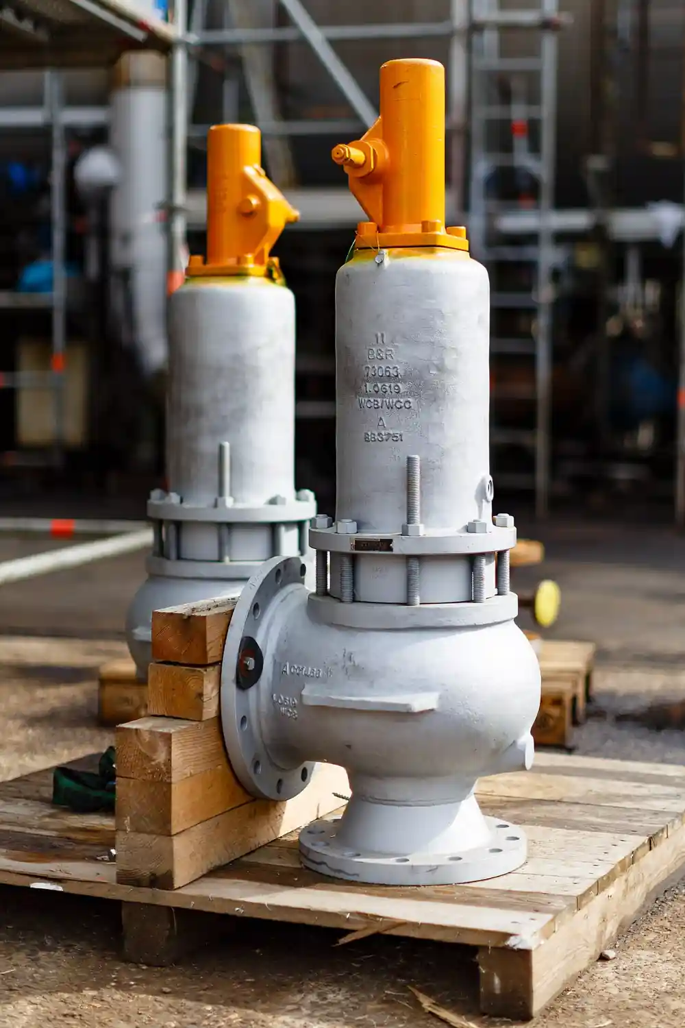
A rupture disk is a one-shot, non-reclosing pressure relief device: a thin calibrated membrane, usually metal or graphite, held between flanges or in a holder, engineered to burst open at a precise differential pressure and stay open. Where a safety relief valve senses overpressure and re-closes, a rupture disk sacrifices itself, giving in one instant the full-bore opening that reclosing devices can only approach. It is the relief device of record for runaway reactions, fouling and polymerizing fluids that would bind a valve seat, toxic service where leakage through a seated valve is intolerable, and as a deliberate isolation barrier in front of a valve to keep it chemically clean until the moment it is needed.
The specification problem is that everything about a rupture disk is statistical arithmetic around one number. Burst pressure is set at manufacturing, verified by bursting samples from the same lot, and stamped with a tolerance; the disk then lives in service at a fraction of that number, and the distance between operating pressure and stamped burst, the operating ratio, decides whether it survives pulsation and fatigue or opens early and shuts the plant down. Temperature shifts the burst point, backpressure changes which pressure difference the disk actually sees, and corrosion thins the dome toward a surprise. This page does the arithmetic the way a relief engineer files it: disk types by loading mechanism, tolerance and manufacturing range math, the ASME UG-127 and API 520 sizing frame, tandem and isolation arrangements, and the RFQ lines that make lot certificates and burst data part of the purchase.
This page treats the rupture disk as a calibrated sacrificial instrument: forward domed and reverse buckling mechanics, burst tolerance and manufacturing range arithmetic, operating ratio rules that decide fatigue life, ASME UG-127 and API 520 sizing and stamping, tandem and valve-combination arrangements, and the RFQ lines that attach lot certificates to the hardware.
Chapter 1 / 06
What a Rupture Disk Is and What Is Being Decided
The device earns its place by doing what a reclosing valve structurally cannot. It seats with zero leakage because a continuous membrane, not a lapped metal pair or a spring-loaded plug, is the pressure boundary. It opens to the full bore of its holder with no chatter, no simmer, and no moving parts to bind in fouling service. It reacts in milliseconds, fast enough to matter on deflagration and runaway reaction duties. And it costs a fraction of a coded valve of the same bore. The price of those virtues is permanent: once it does its job, the process is open to atmosphere or flare until the disk is replaced, which is why the engineering decision is never disk versus valve in the abstract, it is which failure mode the protected system can afford, spill-and-shutdown or lift-and-reseat.
What is being decided, concretely, is five linked quantities and one arrangement choice. The quantities: stamped burst pressure and its tolerance; manufacturing range, the band within which the maker may land the actual burst; operating ratio, maximum steady operating pressure as a fraction of stamped burst; disk temperature at the moment of overpressure, which shifts burst strength; and backpressure, which converts gauge set points into the differential the disk actually responds to. The arrangement: disk alone as the sole relief device, disk upstream of a safety relief valve to isolate it from the process, tandem disks with a three-way valve between them to allow replacement without shutdown, or disk downstream of a valve for low-torque isolation of a vent header. Each arrangement changes the code arithmetic, the capacity credit, and the monitoring requirement, and Chapter 5 works them in order.
The neighbors in the relief family matter for honesty. A safety relief valve, the reclosing spring device, remains the default single-device protection for clean service because it closes and the process continues. The disk takes over where the fluid is fouling, crystallizing, or polymerizing; where the required relief rate exceeds what an economical valve can pass; where toxic or high-purity service cannot accept seat leakage; and where reaction chemistry can outrun a valve's opening dynamics. A knife gate valve or other isolation valve is not a relief device at any point in this conversation, and a globe valve or butterfly valve controls flow, it does not protect vessels; keeping those categories straight is half of a relief review. The disk also serves as a rupturable secondary barrier on transport tanks, exchanger shells, and positive displacement pump discharge guards, small applications where a coded valve is disproportionate.
One vocabulary note that procurement files should respect: rupture disk is the ASME term, rupture disc and bursting disc the same device in British and ISO documents, and all three name one product family. A specification that orders a disc and a disk has ordered two of the same thing.
Chapter 2 / 06
Burst Mechanics and Set Pressure Arithmetic
Two loading mechanisms cover nearly the catalog. Forward domed, or forward acting, disks are formed as a shallow dome with process pressure on the concave side: the membrane carries tension, and burst initiates when hoop stress at the apex exceeds the material's strength, opening by a combination of tearing and petaling. Forward domed disks are simple, tolerant of rougher holders, and available from low millibar duties to hundreds of bar; their weakness is fatigue under pressure cycling and pulsation, because the dome is loaded in tension all its life. Reverse buckling disks are installed with the dome against the process, so the membrane carries compression: at a critical differential the dome buckles through in a few hundred microseconds, and in pre-scored designs the buckling energy drives the score lines open to a full bore in the same instant, while knife-blade designs flip the disk onto a cutting ring that does the opening. Reverse buckling disks hold tighter tolerances, resist pulsation far better because buckling is a stability event rather than a slow tension creep, and permit the highest operating ratios in the family.
Burst pressure is a certified number, not an aspiration. The manufacturer bursts samples from each lot at the specified temperature and certifies a stamped burst pressure with the ASME tolerance: for stamped bursts at or below 40 psig the tolerance is plus or minus 2 psig, and above 40 psig it is plus or minus 5 percent. Manufacturing range is the band around the nominal within which the lot average may fall and still ship: a disk ordered at 100 psig nominal with a minus 10, zero range may be certified anywhere in that band, and the stamped value becomes the set point of record for code calculations. The buyer's arithmetic is therefore: take the stamped burst, apply the tolerance to get the possible actual burst window, check that the top of the window still protects the vessel at or below its maximum allowable working pressure, and check that the bottom of the window sits far enough above maximum operating pressure that fatigue and statistical scatter do not eat it. That second check is the operating ratio.
Operating ratio guidance is published by disk makers and embedded in API 520 sizing practice: conventional forward domed disks are commonly limited to 70 to 80 percent of stamped burst in steady service, lower under heavy cyclic duty; reverse buckling pre-scored disks run 85 to 90 percent; graphite disks, which tolerate little cycling, hold similar or tighter limits. Exceeding the guidance does not fail the code stamp, it quietly converts the disk into a fatigue specimen: each pressure cycle works the dome, burst strength migrates downward, and the disk opens one ordinary Tuesday at normal operating pressure. Every premature burst investigation that ends with a shrug started with an operating ratio that was treated as a suggestion.
Temperature moves the burst point and belongs in every line of the arithmetic. Metal strength falls with temperature, so a disk certified at ambient bursts lower when hot; makers publish burst-versus-temperature curves and require the specification to state the disk temperature at relief conditions, not the vessel design temperature guess. A disk specified at the wrong temperature can be off tens of percent, which dwarfs every other tolerance in this chapter. Backpressure is the second correction: a disk responds to differential, so constant superimposed backpressure adds directly to the gauge set point, and built-up backpressure in the vent header during relief changes the opening behavior of downstream equipment. Specify whether the stamped burst is a differential or a gauge figure and make the vent header design agree with it.
Capacity is the last piece of physics. Once open, a rupture disk behaves as a sharp-edged orifice of its bore with a discharge coefficient, and ASME UG-127 and API 520 Part I supply the sizing equations for gas, vapor, and liquid relief, with the stamped capacity KR factor combining coefficient and hardware losses. The code stamp UD, applied to certified disks and their holders, is what makes the stamped capacity a legal number, and the combination rule for a disk installed upstream of a valve carries a capacity derating factor of 0.9 on the pair, a detail Chapter 5 returns to because it changes valve sizing, not just disk sizing.
Chapter 3 / 06
Disk Types, Materials, and Duty Boundaries
The type ladder follows the loading mechanism and adds the special-duty families. Conventional forward domed, plain or slotted with a seal membrane, covers general service from roughly 1.5 bar burst upward, with slotted composite designs reaching below 1 bar by cutting stress-concentrating slots and sealing them with a PTFE or metal film. Reverse buckling, plain, pre-scored, and knife-ring designs, owns high pressure, high cycling, and tight tolerance duty, from a few bar to beyond 1000 bar in the extreme catalog. Graphite disks, machined from resin-impregnated graphite, serve corrosion and thermal shock duties that shred thin metal foils, at the cost of fragility and poor cycling tolerance; they are the default on chlor-alkali, acid, and hot oil systems where metal needs exotic liners to survive. Special families close the catalog: sanitary disks with tri-clamp or insert holders for food and pharma, PTFE-lined and tantalum-faced disks for aggressive chemistry, explosion vent panels for deflagration suppression on vessels and silos, which are rupture disks by another engineering name, and vacuum supports, separate elements that back a thin disk against collapse when the protected side can see sub-atmospheric pressure.
Materials ladder by chemistry and temperature exactly like any wetted pressure boundary. Stainless steel, 316 and 316L, is the default foil and covers water, steam, air, and hydrocarbons to moderate temperatures. Nickel and Inconel alloys hold hot alkaline and sour service and retain strength at temperature better than stainless. Tantalum faces hydrochloric acid duties that nothing cheaper survives. Aluminum appears in low-temperature and low-pressure composites. Graphite, as the body rather than a facing, owns the corrosion list from dilute to concentrated acids at temperatures where organic seal films have already left. The holder and companion hardware are carbon steel or stainless by line class, and the wetted seal films inside composite disks, typically PTFE or FEP, are chemistry items that must be reviewed against solvent attack, because a dissolved seal film turns a slotted disk into an open slot at zero notice.
Duty boundaries, sentence by sentence. Steady clean service with modest relief rate: a coded reclosing valve alone is usually the better answer, and the disk adds itself when leakage, fouling, or speed argues. Heavy pulsation near set pressure: reverse buckling, chosen precisely because tensile fatigue is its enemy's weakness, not its own. Cycling service above the guidance ratio: no disk type, redesign the process margin or change the protection concept. Corrosive chemistry: graphite or lined metal, with the lining qualified against the full cleaning regime as well as the process. Vacuum or pump-out possibility: a vacuum support is not optional, an unsupported thin dome collapses inward at a fraction of burst and presents as a mysterious leak or premature failure. Sanitary service: insert-style sanitary disks with certified surface finish, installed in holders that drain and clean in place. Deflagration and runaway reaction: the disk family's home turf, full bore in milliseconds, sized by the reaction energy analysis rather than by pump-around hydraulics.
Disk type
Burst band
Operating ratio class
Hard boundary
Forward domed, plain
approx. 1.5 to 1000 bar
70 to 80 percent
Fatigue under cycling and pulsation
Composite, slotted plus film
below 1 to 10 bar class
70 to 80 percent
Seal film chemistry; film pinholes leak early
Reverse buckling, pre-scored
few bar to beyond 1000 bar
85 to 90 percent
Holder quality matters; knife ring needs alignment
Graphite
0.2 to 50 bar class by size
approx. 80 percent, poor cycling
Fragility; thermal shock handling rules
Sanitary insert
0.5 to 10 bar class
by base type
CIP chemistry must qualify the seal film
Holder hardware is part of the disk, not an accessory thought. A reverse buckling disk depends on a flat, correctly torqued seat and an aligned knife ring; a composite disk depends on the holder's flow path not lifting the seal film; every disk depends on the holder's inlet and outlet bores matching the disk tag. Holders come as threaded, flanged to the line class, sanitary insert, and sandwich styles, and the purchase should always pair disk and holder from one maker and one lot series, because the certified performance is certified as an assembly.
Chapter 4 / 06
Key Specification Parameters
The decode table carries the arithmetic of Chapter 2 as datasheet rows. A blank row in a disk RFQ is not an omission, it is an invitation for the maker to choose the option that ships fastest.
Parameter
Typical spread
What it decides
Stamped burst pressure and tolerance
per ASME: plus/minus 2 psig to 40 psig, 5 percent above
The legal set point and its scatter window
Manufacturing range
minus ranges to zero-range by type
Where the lot may land; drives vessel protection check
Operating ratio
70 to 90 percent by type
Fatigue life and premature burst risk
Disk temperature at relief
ambient to 500 deg C by material
Burst derating; certification temperature
Backpressure basis
atmospheric, constant superimposed, built-up
Whether set is differential or gauge; vent sizing
Bore and capacity basis
DN25 to DN600 class; KR stamped
Relieving capacity credit under UG-127
Material and linings
316L, nickel, Inconel, tantalum face, graphite, PTFE film
Chemistry survival incl. cleaning regime
Vacuum support
required when sub-atmospheric possible
Collapse prevention at partial vacuum
Arrangement and monitoring
single, tandem with 3-way, upstream of valve, sensor
Code capacity credit and replacement practice
Certificates
UD stamp, lot burst report, polymer K factor
Code acceptance and traceability
The set-pressure row is a system question, not a disk question. The vessel's maximum allowable working pressure caps the stamped burst, the protection logic decides burst versus vessel margin, and the operating pressure decides everything below it through the ratio. Buy the disk after the relief calculation, never before, and make the stamped burst the number the calculation justified rather than the number the last purchase happened to carry, which is how plants inherit disks stamped for a process that no longer exists.
The temperature row deserves insistence. Makers certify each lot at a stated temperature; quoting a burst at ambient for a disk that will relieve hot fluid silently moves the actual burst by the full slope of the material curve. The same insistence applies to backpressure: a tandem installation with a sealed interspace sees a different differential world from a disk venting to a shared header, and the certification must name the basis. When the RFQ carries both numbers, the lot test conditions match service and the certificates mean what they say.
The monitoring row is where modern practice has moved. A burst disk tells no one it has opened until the process behaves strangely; burst sensors, telltale wires in the holder read by the control system, and pressure switches in the interspace convert the event into an alarm. On any installation whose unannounced relief is an environmental or safety report, a burst indication device belongs in the same purchase order as the disk, and the interlock review belongs in the same meeting as the relief sizing. A pressure transmitter or pressure sensor on the protected vessel remains the primary trend witness for everything below burst.
The certificate row is the delivery ticket in code jurisdictions: UD stamp under ASME VIII for certified disks and holders, lot burst test reports against the certified tolerance, material certificates, and the KR capacity factor for the assembly. European PED contexts carry an equivalent conformity chain. A disk without its lot papers is scrap metal with a good story, because the code credit, and most insurance audits, attach to the stamped and documented assembly only.
Chapter 5 / 06
Selection Decision Factors and RFQ Language
The decision sequence runs relief logic first, hardware second, and paperwork throughout.
Establish the protection basis: scenario relief rate from the energy balance or reaction analysis, maximum allowable working pressure of the vessel, and required set at or below it. This is API 520 Part I and UG-127 territory, and it is the same calculation whether the final device is a disk or a valve.
Fix operating pressure and its realistic maximum, including startup, regeneration, and upset operation. Compute operating pressure against candidate stamped bursts and select the disk type whose ratio guidance covers it with margin.
Fix disk temperature at relief and backpressure basis. These two corrections move the burst more than any tolerance; certify the lot at these conditions.
Select material and linings against full chemistry including cleaning and regeneration cycles, and decide vacuum support necessity by walking every path to sub-atmospheric pressure, pump-out, steam condensation, cold drain.
Select the arrangement: single disk, tandem with three-way switching for online replacement, disk upstream of a safety relief valve with the 0.9 combination capacity factor, or disk downstream for header isolation. Add burst indication wherever unannounced relief is unacceptable.
Size the bore for capacity with the stamped KR, check the vent header for built-up backpressure, and confirm every flange in the path matches the line class.
Write the RFQ with the Chapter 4 rows, the certificate list, and a spare-lot strategy, and review quotes against the same rows.
Cost behavior is bimodal: the hardware is cheap and the wrong one is expensive. As a planning spread: a standard 316L forward domed disk in a matched flanged holder sits at the baseline of the family; reverse buckling pre-scored assemblies run roughly 1.5 to 2.5 times that; graphite assemblies price by bore, commonly 2 to 4 times stainless at moderate sizes; exotic facings and sanitary builds add by material; tandem installations are two disks plus a three-way valve; and burst sensors add a small instrument line each. Against a coded valve, the disk hardware is nearly always cheaper; the honest comparison is lifetime cost including the shutdown a burst implies, which is why arrangement choice, online-replacement tandems and valve isolation, is where the real money decision lives.
Option pair
Relative cost
What you gain
What you pay in
Forward domed vs reverse buckling
1.0 vs 1.5 to 2.5
Ratio to 90 percent, cycling tolerance
Price, holder precision
Stainless vs graphite disk
1.0 vs 2 to 4
Corrosion and thermal shock survival
Fragility, handling discipline
Single vs tandem with 3-way
1.0 vs 2.5 to 3
Online replacement, no shutdown
Hardware, interspace monitoring
Disk alone vs disk plus valve combo
1.0 vs 3 to 6
Valve isolation from fouling, reseating
0.9 capacity factor, leak detection need
Blind install vs burst sensor added
1.0 vs 1.05 to 1.15
Announced relief event
One more instrument loop
The RFQ checklist writes out as: stamped burst with tolerance and the vessel MAWP it protects; manufacturing range named; operating pressure and ratio basis; disk temperature at relief and certification temperature; backpressure basis and vent header state; disk type, material, lining, and vacuum support yes or no; holder style, bore, and line class with flange standard; arrangement, single, tandem, or valve combination, with monitoring devices named; certificates, UD stamp, lot burst reports, material certificates; spares as a second lot from the same design with its own certificates. Vendors answering every line can be compared; vendors answering some of them are quoting the disk they stock, not the disk the relief calculation bought.
System context closes the selection. The relief path is only as good as its weakest steel: the outlet flange class, the vent header sizing, the drain and trap arrangements that keep rain and condensate off the disk's downstream face. Isolation valves in the relief path are code-limited and, where permitted, are full-bore ball valve or gate valve patterns with locked-open administration, never a throttling globe valve left half-shut by a helpful operator, and the disk's neighbor in the line, be it a check valve or a butterfly valve on the header, must not flutter or shed fragments into the opening. The relief review that reads the whole path, not just the tag, is the one that sleeps.
Chapter 6 / 06
Installation, Standards, Failure Modes, and Maintenance
Installation discipline is short and unforgiving. Handle disks by the holder edges, never touch the dome, and refuse any disk with a dent, scratch, or fingerprint-scale mark in the dome: a fingertip dent is a stress riser with a burst pressure attached. Install with the flow arrow and dome orientation the tag states, reverse buckling disks dome-into the process, forward domed concave-to-process. Torque holder bolts to the maker's pattern and value, crossing in stages, because an uneven seat leaks or buckles the geometry early. Replace the holder gasket at every disk change as a rule, use only the maker's gasket, and leave the disk's protective packaging on until the flange faces meet. No paint, sealant, or optimism on the disk, and no lifting of the line's blinds until the tag and the relief calculation have been read against each other by two people.
Commissioning is a paperwork event more than a field event: verify stamped burst, tolerance, lot number, and certificate chain against the relief calculation and the vessel MAWP; verify disk temperature rating against service; verify orientation and holder torque record; log the lot into the spares register; and test the burst indication loop end to end. The relief path itself is proven by the hydrotest and the vent header's own documentation; the disk is proven by its lot's burst test, which is why those papers ship with the disk and live in the inspection file, not in a drawer.
The standards frame: ASME VIII Division 1, UG-127, governs rupture disk devices as pressure relief, sets the certification and tolerance structure this page quotes, and with Appendix 11 and the UD stamp rules defines what a Code disk means; API 520 Part I and its sizing companions govern relief calculation practice and the ratio guidance culture; API 521 governs the overpressure protection study that decides where disks belong; and the National Board publishes the inspection and installation practice that jurisdictional inspectors work from, including the rules for valves in relief paths and for combination capacity credit. PED 2014/68/EU carries the European conformity chain. These documents, cited by designation in the RFQ, are what turn a foil circle into a legal relief device.
Failure modes rank cleanly. Premature burst leads, and its causes rank within it: operating ratio exceeded by a quietly raised operating pressure, pulsation and cycling fatigue on forward domed disks, corrosion thinning the dome, temperature excursions derating strength, and installation damage acting as an instant stress riser. Leak-through follows: pinholes in composite seal films, hairline corrosion cracks, and seat defects, presenting as trace process in the vent or interspace pressure drifting, which is exactly what tandem interspace gauges and telltale sensors exist to announce. Vacuum collapse of an unsupported disk appears as a dish-shaped surprise found at turnaround. Fragment entry into downstream equipment, largely designed out by pre-scored non-fragmenting types, survives in older knife and plain designs and belongs in the downstream equipment review. And wrong-lot installation, a disk stamped for a different pressure or temperature put in because it fit the holder, is a paperwork failure that only procedure and tag verification catch, which is why the two-person tag read of commissioning exists.
Maintenance is replacement policy, monitoring, and records. Replace disks at every relief event obviously, but also at interval: makers and practice suggest review at one to three years for metal disks in cycling service and on any corrosion evidence, with graphite reviewed more conservatively. Keep at least one certified spare lot on site for every service whose downtime costs more than the disk, and retire spares on the same clock. Monitor what can announce itself, interspace pressure on tandems, burst sensors where installed, vessel pressure trend against the ratio, and treat any drift toward ratio limits as the maintenance trigger it is. And file everything, lot numbers, certificates, torque records, relief calculations, in one inspection folder, because when a disk does its job at 3 a.m., the first question the authority asks for is the file, and the second is whether the replacement is already on the shelf.
FAQ
What is the difference between a rupture disk and a rupture disc?
None. Rupture disk is the ASME term, rupture disc and bursting disc the British and ISO spellings for the same non-reclosing device. A specification using both terms has specified one product twice; pick the ASME spelling for code files and note the synonyms once.
How close can operating pressure run to burst pressure?
By disk type as maker guidance: roughly 70 to 80 percent of stamped burst for forward domed disks, 85 to 90 percent for reverse buckling pre-scored types, and similar caps for graphite. Exceed the guidance and fatigue quietly walks the burst point down toward normal operating pressure, which is the classic premature burst mechanism.
What do burst tolerance and manufacturing range mean on the tag?
Tolerance is the ASME certification scatter around the stamped burst, plus or minus 2 psig up to 40 psig and 5 percent above. Manufacturing range is the band the lot average may fall within at test and still ship; the stamped value inside that band is the set point of record. Check the top of the tolerance window against vessel MAWP and the bottom against your operating ratio.
Can I put a rupture disk in series with a safety relief valve?
Yes, and it is a standard arrangement: the disk upstream keeps fouling or corrosive fluid off the valve seat. Code sizing applies a 0.9 combination capacity factor to the pair, and the interspace needs a pressure gauge or telltale so a pinholed disk is announced rather than discovered.
Why does disk temperature matter so much?
Burst strength falls with temperature, by tens of percent across a normal service range for some metals. A lot certified at ambient will burst meaningfully low when relieving hot fluid. Specify the disk temperature at relief conditions and have the lot certified at that temperature; it is the largest single correction in the arithmetic.
How do I know a disk has burst or is leaking?
Announced designs exist for both: burst sensors and telltale wires alarm the burst, and tandem installations monitor interspace pressure, which rises on a pinhole in the upstream disk. Unmonitored disks are found by process behavior or inspection. On any service where unannounced relief is reportable, the indication loop belongs in the same purchase order as the disk.
What does the UD stamp actually certify?
That the disk and holder assembly was lot-tested and certified under ASME VIII rules: stamped burst within code tolerance at the stated temperature, and a stamped capacity basis with its KR factor. It is what makes the relief calculation legally closeable, and it is why the lot certificates ship with the hardware and live in the inspection file.