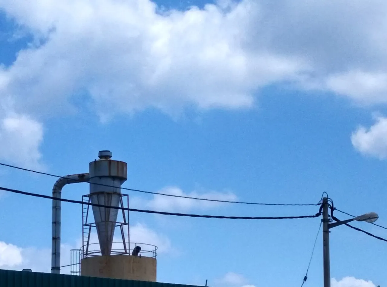
A thermal oxidizer is an air pollution control device that destroys volatile organic compounds, hazardous air pollutants, and odorous organics in a process exhaust stream by raising the gas to an oxidation temperature, typically 760 to 980 deg C, and holding it there for a designed residence time, usually 0.5 to 2.0 seconds, with enough turbulence to mix the organics with oxygen. Hydrocarbons leave as carbon dioxide and water, and the destruction efficiency, reported as DRE, reaches 98 to 99.99 percent when temperature, time, and turbulence are correctly engineered together. Heat is recovered either in a metallic shell-and-tube exchanger on a recuperative unit or in ceramic beds that cycle between storing and releasing heat on a regenerative unit, and a catalyst can lower the required operating temperature to the 300 to 450 deg C band.
Procurement engineers meet these units on printing and coating lines, chemical and polymer plants, semiconductor and battery solvent exhaust, pharmaceutical suites, soil remediation projects, and wood products dryers. The decision this page settles is which oxidizer architecture fits the stream: a direct fired unit for dilute flow with high concentration spikes, a recuperative unit for steady continuous loading, a regenerative unit for large flows with low concentration, or a catalytic unit where poisons and temperature windows permit. The answer lands as an RFQ line set, flow and speciation and inlet LEL and required DRE and heat recovery type, and every chapter below feeds that line set so the unit is bought against the permit it must satisfy rather than against a brochure.
This page treats the thermal oxidizer as a purchasing object: what temperature, residence time, and turbulence actually deliver a permitted DRE, how DFTO, recuperative, regenerative, and catalytic architectures divide the duty between them, which specification lines decide compliance and operating cost, and how the whole decision folds into a defensible RFQ. It is written for engineers who issue purchase specifications against emission permits, not for readers who want a brochure summary.
Chapter 1 / 06
What a Thermal Oxidizer Is and What Is Being Decided
The defining act of the machine is thermal destruction, not filtration and not absorption. A wet scrubber removes acid gases and some particulate by liquid contact, a dry scrubber reacts acid gas across a sorbent bed, a bag filter collects dust on fabric, and an electrostatic precipitator charges and collects particles in a field. None of those devices does anything to a vapor phase hydrocarbon: a toluene molecule passes a baghouse untouched. The thermal oxidizer is the unit in the air pollution control train that converts that molecule to carbon dioxide and water by sustained high temperature, which is why it sits at the end of the train, after any particulate control that protects its internals, and why its sizing is driven by gas chemistry rather than by particle loading.
What is being decided in this purchase is four commitments at once: an architecture that matches the flow and concentration profile, a destruction efficiency that satisfies the emission permit with margin, a heat recovery scheme that keeps fuel cost defensible, and a safety design that handles the inlet Lower Explosive Limit honestly. A buyer who chooses a regenerative unit for a stream that swings rich will fight high temperature trips; a buyer who chooses a catalytic unit for a stream carrying siloxanes will replace poisoned catalyst on a schedule nobody budgeted. The four commitments are one purchase order, and the point of this page is that they can be checked on paper at RFQ stage.
The combustor inside the unit is a burner assembly, and the burner is a component, not the product. An industrial burner of the type used on fired equipment supplies the auxiliary heat that brings the stream to oxidation temperature on startup and holds it when the organic loading cannot sustain the reaction alone. Around that burner sit the oxidation chamber, the heat recovery system, the fan or blower that moves the gas, the stack, and the controls. A flame detector supervises the burner under the same burner management logic any fired heater uses, and a flame arrester or detonation arrester may be required on the inlet duct where the stream can approach flammable limits. The buyer specifies the system; the burner maker is a subcontractor to it.
Standards and codes frame the datasheet. In the United States, oxidizer performance is enforced through Clean Air Act permitting, with New Source Performance Standards and National Emission Standards for Hazardous Air Pollutants subparts naming the DRE and monitoring expectations by industry, commonly 98 percent DRE as a floor and 99 percent or better where the subpart or the state permit demands it. Fire and explosion safety on the inlet and combustion side follows NFPA 86, the standard for ovens and furnaces, which fixes safety shutoff valves, purge sequences, and the concentration limits described in chapter 2. Pressure vessel and structural design follows local mechanical code, and the stack and monitoring follow the permit itself. A datasheet that quotes a DRE without naming the governing subpart is a price tag, not a specification.
The neighbors in the control train deserve naming in the RFQ too. A cyclone separator or a bag filter upstream protects ceramic media and catalyst faces from particulate. A mist eliminator knocks out aerosol droplets that would otherwise flash in the inlet. Downstream, a gas analyzer or a continuous emission monitor proves the DRE, a thermal mass flowmeter reports the treated volume, and temperature transmitters and pressure transmitters across the beds give the operating evidence the permit audit reads. On streams with particulate carryover, a regenerative blower or a turbo blower moves gas through beds whose pressure drop is watched on a differential reading, and a rupture disk protects any sealed section that can be over pressurized during a fire or explosion event. Stating the whole train in the RFQ lets one supplier own the performance number instead of five vendors dividing the blame.
Chapter 2 / 06
How Thermal Oxidation Destroys Organics
The chemistry is combustion without an open flame front in the working section. Above roughly 700 deg C, and reliably at 760 to 980 deg C, hydrocarbon molecules react with oxygen fast enough that a gas element held at temperature for a fraction of a second to two seconds is stripped to carbon dioxide and water. The engineering shorthand is the three Ts: temperature, time, and turbulence. Temperature sets the reaction rate, which roughly doubles with each 10 to 15 deg C rise in this band; time gives slow species such as chlorinated or high molecular weight solvents enough residence to finish; turbulence mixes oxygen into every corner of the flow so no streamline shortcuts the chamber. Fail any one of the three and the DRE falls even if the thermocouple reads the right number, because the thermocouple sits in one place and the gas does not.
Destruction efficiency is the governing number and it is not a single point. Design practice quotes 98 percent as the common permit floor, 99 percent for many state and federal subparts, and 99.5 to 99.99 percent where a stream carries a listed hazardous air pollutant at meaningful loading. The number is fixed by the hardest compound in the stream, not the average: chlorinated solvents, heavier ketones, and some oxygenates need the upper end of both temperature and time, and a chamber sized on toluene conversion will undershoot on methylene chloride unless the specification names the hard species. This is why the RFQ must carry the speciation table and not just a total VOC number, and why a quotation that guarantees a DRE without asking for speciation should be read as a price, not a promise.
Concentration limits are safety limits. The Lower Explosive Limit is the minimum concentration at which the vapor air mixture propagates flame at stream conditions, and NFPA 86 practice and its analogues keep the oxidizer inlet conservatively below it, with 25 percent of LEL the classic limit for unsupervised operation and up to 50 percent of LEL acceptable with continuous monitoring and interlocked shutoff, using a flammable gas analyzer where the stream is not otherwise characterized. When process upsets push the stream rich, the control system admits dilution air to hold the limit, or the unit takes a high LEL trip and the process vents to a bypass or holds. Stream heating value also decides fuel economics: roughly 40 to 60 kJ per standard cubic meter of heat release can carry a well insulated unit with no auxiliary fuel at all, a condition called the autothermal point, and knowing where the stream sits against that point decides whether the burner is a startup device or a permanent consumer of gas.
Heat recovery is where the architectures separate. A direct fired thermal oxidizer has essentially none: gas goes through the chamber and up the stack, thermal efficiency of the unit as a whole sits near zero to a few percent of recovery, and fuel use is the highest of the family, which is why DFTO duty is reserved for very rich streams, small flows, or intermittent batches where the stream heat value largely pays for itself. A recuperative unit adds a metallic shell and tube or plate exchanger that preheats inlet gas with treated outlet gas, recovering 50 to 75 percent and holding stack temperatures down. A regenerative thermal oxidizer stores heat in beds of ceramic media that the gas flow cycles through, recovering 92 to 97 percent and making it the default for large, dilute, continuous streams. A regenerative catalytic oxidizer beds catalyst on or after the ceramic, dropping the operating temperature while keeping the recovery.
Pressure drop and turndown complete the physics the buyer pays for. A recuperative exchanger adds 25 to 60 millibar of gas path resistance; an RTO adds 15 to 30 millibar across two or more beds of media, rising as the media fouls; downstream of everything the induced draft fan or blower must be sized for the dirty end of that range with margin. Turndown matters on batch processes: an RTO holds its beds hot at low flow and rides through load swings cheaply, a catalytic unit can suffer outlet temperature excursions if the concentration spikes while the catalyst is already hot, and a direct fired unit simply burns more fuel at low load. The fan, the media, and the control philosophy together decide the electrical and fuel bill for the decade after purchase, which is why chapter 4 treats them as specification rows rather than accessories.
Chapter 3 / 06
Oxidizer Architectures and Duty Boundaries
Four architectures cover the catalog, and the differences are worth stating as equipment rather than as marketing tiers. The direct fired thermal oxidizer is a refractory lined chamber with a burner and, on most modern units, at least a modest stack gas heat exchanger for combustion air or a hot side bypass; it is the cheapest capital, the fastest to bring to temperature, the most forgiving of concentration swings, and the most expensive to feed on a dilute stream. The recuperative thermal oxidizer pairs the same chamber with a primary metallic exchanger, so inlet gas arrives preheated at 400 to 700 deg C and auxiliary fuel falls accordingly; metallic exchangers cap outlet service temperatures and stress under cycling, so recuperative units favor steady, continuous, mid sized streams. The regenerative thermal oxidizer runs gas down through a hot ceramic bed into the chamber and back up through a second bed, then swaps the beds on poppet or rotary valves every one to three minutes; with 92 to 97 percent recovery it owns the large dilute continuous duty, at the price of valve wear, media maintenance, and a taller footprint. The catalytic oxidizer, whether recuperative or regenerative in heat layout, passes gas over a precious metal or mixed oxide catalyst that lights off at 300 to 450 deg C, cutting fuel and chamber size, but only for streams the catalyst can tolerate.
Catalyst tolerance is a chemistry gate, not a preference. Silicones and siloxanes, common in personal care, textile, and some electronics processes, deposit silica on the catalyst and kill it progressively; halogenated compounds need special catalyst formulations and run the risk of acid dew point corrosion downstream; phosphorus, tin, zinc, and heavy metals poison active sites outright; and particulate blinding masks the surface even when the chemistry is clean. A responsible catalytic quotation therefore begins with a stream screening and often with a pilot coupon exposure, and the specification should demand a stated catalyst life in hours against the declared speciation, with a guaranteed minimum activity at end of life. Where siloxanes are unavoidable, buyers either place a dedicated activated carbon or media guard bed upstream or accept a thermal unit at higher temperature instead.
Within each architecture there are construction variants that matter to the RFQ. RTOs divide into two bed and three bed (or multi bed) machines: two bed units are compact and cheapest but short circuit a small untreated slug of gas at each valve swap, which matters when the permit reads tight, while three bed units purge the switching bed with treated gas and hold the DRE on sensitive applications; rotary valve RTOs replace the poppet seats with a single rotating interface that gives a near continuous flow and lower signature. Recuperative units divide by exchanger type, shell and tube for durability and temperature, plate for compactness and cost, with the metallurgy of the hot end quoted by alloy against the design outlet temperature. Chamber construction divides by refractory versus modular ceramic fiber lining, with cycling service pushing toward low mass fiber linings that follow the temperature up and down without spalling.
Boundaries deserve the same bluntness. This unit does not remove acid gas, so a stream heavy in sulfur or chlorine chlorides needs scrubbing downstream or the permit needs the byproducts handled, and on chlorinated service the buyer should be asking about a downstream wet scrubber or dry scrubber for the hydrogen chloride formed, plus materials for acid dew point. This unit does not collect particulate, so heavy dust loading needs a bag filter or cyclone separator upstream of the media or catalyst face. This unit is not a flare and not a heat treatment furnace: continuous rich waste gas above the autothermal band with stable composition is often better served by a boiler or process heater that recovers the heat as steam, while the oxidizer earns its place on dilute, variable, or permit bound streams where destruction, not energy, is the product. The architecture map below compresses the boundaries into one table.
Architecture
Heat recovery
Best duty
Avoid when
Direct fired thermal oxidizer
Near none to 40 percent with optional exchanger
Rich, small, or batch streams near autothermal; destruction of hard spikes
Large dilute continuous flow, where fuel cost dominates
Recuperative thermal oxidizer
50 to 75 percent metallic exchanger
Steady mid size flow with moderate concentration
Frequent deep thermal cycling that fatigues the metallic exchanger
Regenerative thermal oxidizer
92 to 97 percent ceramic beds
Large dilute continuous streams, tight DRE with purge design
Tiny flows where valve and media cost never pays back
Regenerative catalytic oxidizer
Ceramic beds plus catalyst at 300 to 450 deg C
Clean streams needing lowest fuel burn and CO signature
Siloxanes, halogens, metals, or particulate that poison or blind catalyst
Catalytic recuperative oxidizer
Metallic exchanger plus catalyst
Compact plants, printing and coating ovens on clean solvents
Same catalyst poisons; high temperature excursions that overheat the bed
The table reads as capital versus fuel: recovery percentage climbs down the list while sensitivity to stream chemistry climbs with it. A useful rule quoted across supplier engineering guides is that regenerative heat recovery pays its capital premium once the stream exceeds roughly 15,000 to 30,000 cubic meters per hour or runs continuously enough that fuel at lower recovery overtakes the hardware delta within two to three years. Those thresholds move with local gas and electricity prices, which is why chapter 5 puts energy price into the RFQ block itself.
Chapter 4 / 06
Key Specification Parameters
The table below decodes the datasheet lines that decide whether a quoted unit matches the permit and the process. Each row is a purchase defining parameter; the paragraphs after the table explain what to demand and what a weak answer looks like.
Attribute
Typical range or options
What it decides
Design flow
500 to 300,000 Nm3/h by architecture
Chamber size, bed area, fan class, and the whole cost envelope
Chamber temperature
760 to 980 deg C thermal; 300 to 450 deg C catalytic
DRE headroom against the hardest species in the speciation
Residence time
0.5 to 2.0 s at design temperature
Whether slow compounds finish; chamber volume for the flow
Destruction efficiency
98 percent floor; 99 to 99.99 percent by subpart
Permit compliance and the monitoring that proves it
Heat recovery
DFTO near none; recuperative 50 to 75 percent; RTO 92 to 97 percent
Auxiliary fuel burn across the load profile
Inlet LEL handling
25 percent unsupervised; 50 percent with analyzer and interlock
Dilution air sizing, trip philosophy, and fire safety basis
System pressure drop
15 to 60 mbar across beds or exchanger, dirty end
Fan or blower power and the maintenance signal as media fouls
Valve or diverter type
Two or three bed poppet; rotary diverter; butterfly bypass
Untreated slug at swap, wear parts, DRE on tight permits
Catalyst, if any
Pt or Pd on ceramic honeycomb or bead; mixed oxide
Light off temperature, poison tolerance, quoted life in hours
Materials and lining
CSTG shell, ceramic fiber or castable refractory by cycling duty
Shell temperature, thermal cycling life, and corrosion basis
The DRE row is where quotations blur. Demand the DRE stated per the governing subunit and per the hardest listed compound, at the minimum temperature and the maximum flow the vendor will guarantee simultaneously, with the residence time behind it shown as a calculation, not asserted. Ask what happens at turndown: a unit that holds 99 percent at design flow but slips at 60 percent flow because chamber velocity and residence collapse is a compliance risk the process will find on the first batch schedule. The temperature row pairs with it, because raising chamber setpoint is the standard remedy for a marginal DRE, and each 25 deg C of headroom is bought with fuel for the life of the unit unless heat recovery absorbs it.
The LEL row is a safety architecture, not a number copied into a datasheet cell. The 25 and 50 percent of LEL practices from NFPA 86 and its international analogues translate into hardware: a flammable gas analyzer on the inlet where composition varies, automatic dilution air dampers sized for the credible worst slug, safety shutoff valves on the gas train, purge sequences before lightoff, and a high heating value trip that fails the process to a safe state. Where the stream can swing rich suddenly, for instance on batch reactor vents, the buyer should be discussing fast acting analyzers and diversion logic in the same meeting as the DRE, because the same upset that trips the unit is the one the permit officer reads about. The heat recovery rows then set the operating cost: as a planning number, each additional 10 points of recovery on a continuous 50,000 Nm3/h stream at a few hundred degrees of rise is worth a meaningful fraction of the annual fuel bill, which is why the architecture choice amortizes in energy.
Load profile
Architecture fit
Reason in one line
Continuous, dilute, over 30,000 Nm3/h
Regenerative thermal oxidizer, three bed with purge
92 to 97 percent recovery makes fuel minor; purge bed holds DRE
Continuous, moderate, 5,000 to 30,000 Nm3/h
Recuperative thermal oxidizer
Metallic exchanger recovery without media and valve complexity
Batch, spiky, rich slugs near 25 percent LEL
Direct fired unit with dilution and bypass logic
Simple chamber tolerates swings that would trip or overheat others
Clean solvents, fuel sensitive, CO limited
Regenerative catalytic oxidizer
300 to 450 deg C operation cuts fuel and carbon monoxide
Siloxane bearing personal care or textile stream
Thermal RTO with guard bed, not catalyst
Silica deposition poisons catalyst on a short clock
Chlorinated solvent service
Thermal unit with acid gas aftertreatment
HCl formed needs scrubbing and dew point materials anyway
The second table is the screening pass most engineering offices run before any vendor call, and the RFQ should state which row the project sits in and why, because it anchors the vendor to the right architecture before pricing enthusiasm takes over. A supplier invited on the wrong row quotes confidently against the wrong duty, and the error surfaces in year two as a fuel bill, a poison claim, or a trip log.
Chapter 5 / 06
Selection Decision Factors and RFQ Language
The decision sequence is short enough to run as a checklist in a specification meeting, and each step eliminates a class of quotations before price comparisons begin.
Assemble the stream data honestly: design and minimum flow, temperature and moisture, full speciation with the hard compounds flagged, and the concentration profile over the production week including batch spikes.
Convert the profile into inlet LEL terms and mark every operating state that exceeds 25 percent of LEL, because those states dictate dilution, analyzer, and trip scope.
Fix the permit requirement: governing subpart, required DRE, outlet limits including carbon monoxide and nitrogen oxides, and the monitoring the permit imposes.
Pick the architecture row from the chapter 4 load profile table, then challenge it once against fuel price and utilization: the recovery percentage amortizes against energy, not against brochure claims.
Screen catalyst viability if a catalytic row is attractive: poisons, halogens, particulate, and expected temperature excursions, with a stated catalyst life in hours.
Set the mechanical basis: chamber temperature and residence with DRE at minimum temperature and maximum flow, heat recovery type and percentage, pressure drop dirty end, valve or diverter type, lining for the cycling profile.
Define the safety package: LEL analyzer, dilution air, gas train with safety shutoff valves, purge and lightoff sequence, flame supervision, and bypass philosophy on trip.
Fix the verification evidence: performance test protocol, DRE guarantee conditions, fuel consumption guarantee at stated load, and the instrumentation list the permit audit will read.
Against neighboring control equipment, the comparison a specifier needs runs as follows, and it belongs here in the selection chapter rather than in the page title. The wet scrubber and dry scrubber handle acid gas and some aerosol, not vapor phase organics. The bag filter and the electrostatic precipitator collect particulate, not carbon. The cyclone separator protects downstream equipment from dust. The mist eliminator removes droplets. Only the oxidizer destroys the molecule, and where a stream carries both particulate and organics the honest train is collection then oxidation, in that order, with the oxidizer protected by the collectors. Where a stream is dominated by a recoverable solvent at high concentration, recovery by carbon or condensation often precedes oxidation so the oxidizer sees only the tail, and the RFQ should state whether recovery is in scope so vendors size on the residual load.
Utilities decide more than hardware does. The unit needs a fuel source, natural gas, LPG, or dual fuel, sized for startup and for the lean end of the load profile; it needs electrical power for the fan or blower, which is often the largest operating cost after fuel on a regenerative machine; it needs instrument air for valves and dampers; and on catalytic units it may need a heated bypass for excursions. Winterization and heat tracing on sampled lines, a stack height consistent with dispersion modeling, and plot space for tube pull, media access, and stack guy clearances belong in the RFQ block because they change the bid, not the brochure. Where the site runs a heat recovery steam or oil loop, the buyer should say so, because an energy-from-waste buyer and an abatement buyer get different machines from the same vendor catalog.
The RFQ block should be written once and reused. A complete block reads: design, normal, and minimum flow in Nm3/h with temperature and moisture; speciation table with each compound, loading, and the hard species flagged; concentration profile including maximum credible slug; inlet LEL basis and required handling class; governing subpart and required DRE, with outlet limits for CO and NOx; preferred architecture with the load profile row named, or a request for reasoned alternatives; chamber temperature and residence time basis; heat recovery type and guaranteed percentage; system pressure drop dirty end; valve or diverter type and purge design; catalyst formulation and guaranteed life if catalytic; burner fuel and turndown; lining and shell design basis for the cycling profile; safety scope including analyzer, dilution, gas train, purge, and flame supervision philosophy; materials for any halogen or sulfur bearing service and the aftertreatment expected; instrumentation list including the flowmeter, analyzers, and transmitters the permit requires; performance test and guarantee conditions; and utilities with prices for the energy evaluation. A quotation returned without the DRE guarantee conditions or the fuel guarantee at stated load is incomplete at any price.
Chapter 6 / 06
Installation, Standards, Failure Modes, and Maintenance
Installation quality decides whether the unit reaches its guaranteed numbers. Ducting to the unit should arrive with the moisture knocked down where condensation would load the media, and the inlet run should carry the mist eliminator or knockout the design calls for, not one sized by convenience. The unit foundation carries a tall, cycling mass: refractory dryout follows a vendor bakeout curve measured by thermocouple, and skipping it converts lining water to steam inside the shell. Fan and blower bases isolate vibration, expansion joints take duct growth, and the stack and sampling platforms land where the permit said they would, because a monitoring port in the wrong place is a permit finding regardless of the DRE behind it. Burner lightoff follows the NFPA 86 style sequence the controls vendor implemented: purge, safety shutoff valve proof, ignition, and flame detector confirmation before the main gas valve opens.
Commissioning proves two numbers: destruction and energy. The performance test runs the governing compound set at design flow and reads the inlet and outlet gas analyzer pair against the DRE guarantee, with the thermal mass flowmeter confirming the treated volume. The fuel test runs the unit at the stated normal load and reads the gas meter against the consumption guarantee. Both belong in the purchase contract as witnessed tests with defined methods, because the alternative is discovering in year one that the guarantee assumed a leaner stream or a tighter DRE than the permit language the plant actually holds. Controls commissioning also proves the safety stack: a simulated high LEL signal that opens dilution, a simulated flame failure that closes the safety shutoff valves, and a purge interlock that blocks lightoff until the timed volume clears.
Failure modes in service follow a short and predictable list. RTO poppet valve seats and bearings wear, seen first as short duration pressure bumps in the chart and later as untreated slugs at swap on tight permits; the remedy is seat refurbishment on schedule rather than after the analyzer notices. Ceramic media fouls and fragments at the cold face when particulate gets past upstream collection or when condensation wets the bed, raising pressure drop across the beds and stealing fan margin, so the differential pressure reading is a maintenance signal, not decoration. Catalyst deactivates by poisoning or blinding and announces itself as rising outlet VOC at unchanged temperature, first slowly and then on a knee; the guard bed and the quoted life in hours are the defenses bought at specification time. Metallic exchangers on recuperative units crack at welds under deep cycling, found as falling preheat and rising fuel. Refractory spalls where cycling discipline is poor. Burner problems track the same list any fired equipment carries, from fuel pressure stability to flame detector sight tube fouling, and the gas train safety shutoff valves get their leak test on the maintenance calendar the code demands.
Maintenance intervals scale with stream cleanliness more than with running hours. A clean, continuous regenerative unit on coating oven exhaust can run a media inspection at two to three year shutdowns with valve seats on an annual check; a stream carrying any particulate or aerosol risk moves media inspection to every shutdown and adds the upstream collector to the same work order. Catalytic units get an annual activity check against the light off curve, with coupon exposure where siloxanes are suspected even in trace amounts. Instrumentation calibration follows the permit calendar: analyzers, the flowmeter, and the temperature and pressure transmitters that feed the compliance record, with heat tracing maintained on sampled lines through winter. Every one of these checks produces a number, and the file of numbers is what the next RFQ uses: the stream profile corrected against real operation, the fuel burn against the guarantee, and the component lives against the quotes. That is how a purchasing file gets smarter instead of just older.
FAQ
What destruction efficiency should I specify?
Start from the governing permit subpart, not from vendor literature. Common floors are 98 percent DRE, with 99 percent and 99.5 to 99.99 percent demanded where listed hazardous air pollutants are involved. Specify the DRE per the hardest compound in your speciation, at minimum chamber temperature and maximum flow simultaneously, and require the residence time calculation behind the guarantee. A single number without those conditions is unenforceable.
When does a regenerative unit beat a recuperative one?
On energy. A regenerative thermal oxidizer recovers 92 to 97 percent of the heat in ceramic beds against 50 to 75 percent for a metallic exchanger, so continuous streams above roughly 15,000 to 30,000 Nm3/h, or smaller streams with high utilization, amortize the extra capital in fuel within a few years. Recuperative units stay attractive at moderate continuous flows where their simpler valve free design and lower profile fit the plot better.
How is inlet LEL handled safely?
By architecture, not by hope. Practice following NFPA 86 keeps the inlet at or below 25 percent of the Lower Explosive Limit for unsupervised operation and allows up to 50 percent with continuous flammable gas monitoring and interlocked shutoff. The hardware behind the number includes dilution air dampers sized for the worst credible slug, safety shutoff valves on the fuel train, and a trip philosophy that fails the process to a safe state on high concentration.
What poisons a catalytic oxidizer?
Silicones and siloxanes deposit silica on the active sites and are the classic killer in personal care, textile, and some electronics streams. Halogenated compounds need special catalysts and create acid byproducts, phosphorus and heavy metals poison directly, and particulate blinds the face. Demand a stream screening, a guard bed where trace siloxanes exist, and a guaranteed catalyst life in hours against your declared speciation.
What does autothermal operation mean for fuel cost?
A unit is autothermal when the organic loading alone supplies enough heat, roughly in the band of 40 to 60 kJ per standard cubic meter of heat release depending on recovery, to hold oxidation temperature with the burner off or at pilot. If your profile sits above that band, a direct fired architecture may burn almost no auxiliary fuel; far below it, recovery percentage dominates and the regenerative choice pays.
How do I size for batch or spiky flows?
Size the chamber on the maximum continuous flow, then check turndown behavior explicitly, holding the DRE guarantee at minimum flow where residence grows but mixing may fall. Add dilution air capacity for the largest credible concentration slug, and review trip behavior: two bed regenerative units short circuit a small untreated volume at each valve swap, so tight permits on batch plants favor three bed purge designs or rotary diverters.
What monitoring will the permit audit read?
Typically a continuous emission monitor or gas analyzer pair proving outlet concentration, a thermal mass flowmeter reporting treated volume, chamber temperature records from redundant temperature transmitters, and pressure or differential readings across beds or exchanger. Calibration records and the instrumentation list belong in the purchase scope, because the audit reads the instruments the RFQ bought.