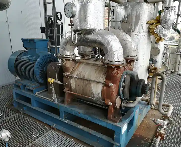
A regenerative blower is an oil free, dynamic air machine in which an impeller carrying dozens of radial blades rotates inside a housing machined with a toroidal side channel. Gas drawn in at the inlet port is trapped between blades, accelerated outward, thrown into the channel, slowed, and scooped up again by the following blades, so a single wheel imparts energy to the same gas many times over between inlet and outlet. The result is a machine that behaves like a multistage compressor in one casing: a single stage typically develops on the order of 100 mbar of differential pressure, larger frames reach about 200 mbar, two and three stage builds extend past 300 mbar, and special stacked multistage versions approach 1000 mbar, across flows from 30 to 2500 m3/h at 50 or 60 Hz. Suppliers also list the identical machine as a side channel blower or ring compressor; the three names describe one construction, and this page uses them interchangeably.
Procurement engineers meet these machines at sewage package plants and aquaculture aeration, on lean phase pneumaticconveying of powders, under CNC routers and printing tables as vacuum hold down, and as sparging and agitation air movers on chemical skids. The decision this page settles is narrow and practical: whether the duty point sits inside the side channel envelope at all, whether one impeller or a staged machine is needed, and which motor, starter or drive, silencer, filter, and protective instrumentation complete the station. The answer lands as an RFQ line set: frame size, stage count, duty point stated in mbar and m3/h, motor rating and enclosure, noise declaration per ISO 2151, and the accessories that keep a 20,000 hour machine from becoming a two season one.
This page treats the regenerative blower as a purchasing object: how the side channel regenerates pressure in real numbers, how to read the published curve and place the duty point on its steep half, what single, two, and three stage construction changes, which protections and accessories a datasheet must carry, and how all of it combines into a defensible RFQ. It is written for engineers who issue purchase specifications, not for readers who want a brochure summary.
Chapter 1 / 06
What a Regenerative Blower Is and What Is Being Decided
The regenerative principle is the difference. A fan wheel adds energy to the gas once; a side channel wheel adds it repeatedly, because the housing channel returns the gas to the blade roots over and over as it travels from the inlet port to the discharge port. Pressure therefore builds along the channel the way it builds through the stages of a multistage centrifugal pump, which is why a wheel running at about 2900 rpm on a 50 Hz supply produces 100 to 300 mbar where a single pass axial fan of the same size produces a few mbar. Nothing in the air path touches anything else: the impeller runs in clearances measured in tenths of a millimeter, there is no oil anywhere in the gas stream, and the only wearing parts are the motor bearings.
What is actually being decided in this purchase is whether the duty point, the intersection of required differential pressure and required flow, sits comfortably inside the published envelope of one frame, or whether the honest answer is a different machine class. Buyers who select on the two endpoints of the curve, maximum pressure or maximum flow, buy the wrong frame twice: maximum pressure happens at nearly zero flow and maximum flow happens at nearly zero pressure, and neither endpoint exists in a real plant. The purchase commits to a frame, a stage count, a motor and its electrical treatment, and a protection package, and each of those four decisions is checkable on paper at RFQ stage.
Against its neighbors, the machine occupies deliberate ground, and the working comparison belongs in the selection chapter. As a vacuum pump the side channel unit covers the shallow and medium band, roughly 100 to 300 mbar below atmosphere, where the liquid ring vacuum pump takes wet gas and deeper vacuum, the rotary vane pump takes smaller flows and deeper vacuum with oil in the stream, and the screw compressor takes the top of the pressure range. On the pressure side, a roots type lobe pump moves more flow at up to about 1 bar, and a screw compressor owns higher pressures. The regenerative blower takes the quiet, oil free, continuous duty middle: enough pressure for aeration and conveying, enough flow for plant scale, and no lubricant to contaminate a diffuser grid or a food conveying line.
Three standards organize the datasheet. Noise emission is declared per ISO 2151, the sound test code for compressors and vacuum pumps, which is what makes one supplier's dB(A) figure comparable to another's. The motor is specified under the IEC 60034 family: rating, insulation class F or H, enclosure IP54 or IP55, and efficiency class IE3 or IE4 per IEC 60034-30-1. Where the machine breathes combustible dust or solvent vapor, ATEX versions built under Directive 2014/34/EU for Zones 1 and 21 or Zones 2 and 22 are a line item, not an afterthought. A datasheet that quotes none of these three is a price tag with a motor attached.
The RFQ should also name the station, not just the machine. A blower station is an inlet filter and silencer on the free side, the machine itself, a discharge silencer, a pressure relief valve or vacuum relief valve set to protect the frame, a check valve on each machine in a duplex set so the running unit cannot spin the idle one, and instrumentation to prove the duty point. Where the inlet air comes from a plant header rather than atmosphere, a Y strainer at the takeoff stops scale and welding debris that a panel filter was never designed to catch. Stating the whole station in the RFQ lets one supplier check port sizes, relief settings, and motor protection in a single pass instead of four arguments at commissioning.
Chapter 2 / 06
How the Side Channel Regenerates Pressure
The mechanism rewards a minute of attention because every selection error traces back to it. The impeller is a disc with many radial blades machined or cast around its perimeter; the housing forms a toroidal channel around that perimeter, open to the blades through a narrow gap. As each blade sweeps past the inlet port it traps a slug of gas and carries it around, accelerating it tangentially. Centrifugal effect and the blade geometry throw the gas outward into the channel, where it slows and gives up its kinetic energy as pressure, then falls back toward the blade roots and is caught by the next blade. The gas therefore travels a helical path through the channel, crossing the impeller dozens of times between inlet and outlet, and each crossing adds another increment of velocity head.
Each individual energy addition is small, a few mbar, which is why the machine is forgiving of its component tolerances; the total comes from repetition. A single stage wheel develops on the order of 100 mbar, with larger frames reaching about 200 mbar. Stacking two or three impellers in series on one shaft, with internal crossovers passing gas from one channel to the next, multiplies the differential: two stage builds hold roughly 200 to 270 mbar, three stage machines pass 300 mbar, and special multistage stacks approach 1000 mbar at reduced flow. Speed governs the whole curve: the same frame on a 60 Hz supply turns about 20 percent faster, moves about 20 percent more air, and develops materially higher pressure than its 50 Hz curve.
The published curve is a steep, nearly straight descending line from shutoff differential at zero flow to zero differential at free delivery, and duty point placement is the whole art. The correct window is the steep upper half of the curve, at flows below the knee and left of the flow peak: there the curve still has slope, so filter loading and seasonal resistance changes slide the operating point up the curve instead of throwing it off the end. Sizing must be done for the dirty filter condition, never the clean one, because resistance growth does exactly that sliding. A duty point selected on the flat right end of the curve is unstable in service: a few mbar of extra system resistance costs a large share of the flow, and the machine spends its life hunting.
Power behavior is the trap for buyers migrating from positive displacement expectations. A gear pump delivers nearly constant volume per revolution regardless of discharge resistance; a regenerative blower, like a centrifugal pump, is a dynamic machine and does not. Its absorbed power rises as the operating point climbs toward shutoff, peaking near zero flow, and falls again only at free delivery on some frames. A blocked discharge or a blinded inlet filter is therefore an overload, not a relief: power climbs, and simultaneously the dwindling airflow can no longer carry the compression heat out of the casing, so discharge temperature climbs steeply, past 100 deg C near shutoff on pressure duty. Thermal trips in this service are almost always selection or maintenance faults, not machine faults.
The same physics sets the noise signature and its cure. Blade passing frequency at the ports generates strong pulsation, and the open port of the unloaded side radiates most of it; typical frames emit 60 to 80 dB(A) at one meter even with silencers fitted, declared per ISO 2151. The effective treatments, in order of value: an inlet silencer with integrated filter on the free side, a discharge silencer, anti vibration mounts so structure borne energy does not reach the building, and finally an acoustic enclosure for machines near a boundary. Speed control trims both flow and noise together: flow falls linearly with speed, pressure with the square, power with the cube, which is why a VFD is often the cheapest energy instrument in the station, and why a soft starter or star delta starter belongs on every direct-on-line motor above a few kilowatts.
Chapter 3 / 06
Types, Construction, and Duty Boundaries
Construction is disarmingly simple, which is the machine's commercial argument. The housing is cast aluminum, usually silicon alloy, split so that the toroidal channel is machined into the two cover halves; the impeller is a cast aluminum disc with blades around its periphery; the shaft runs in greased, sealed ball bearings outside the gas path, designed for 20,000 to 40,000 hours. Ports run from threaded BSP connections of 1 to 2 inch on small frames to PN flanges at DN 80 and above. There is no timing gear, no oil pump, no water seal: maintenance is the air filter, and the filter is why most machines die early. Because the running clearance is a few tenths of a millimeter, any particle hard enough to bridge it can stall or destroy the wheel, so the inlet filter is a component of the machine, not an accessory.
Stage count is the first configuration choice. A single stage machine favors flow: highest capacity per frame and per kilowatt at modest differential, which suits aeration with shallow submergence, air knives, and sparging. A two stage machine, two channels in series on one shaft, trades 10 to 20 percent of flow for differential pressure in the 200 to 270 mbar band, which suits denser filters, deeper tanks, and conveying lines with real length. Three stage frames push past 300 mbar at lower flow, and special stacked multistage machines approach 1000 mbar for niche duties where the alternative is a screw compressor with an oil separator to maintain. Buying stages the duty does not need wastes energy and money in the other direction.
Pressure and vacuum are the same machine read from different ends. Manufacturers publish one curve family per frame and mark pressure operation and vacuum operation separately, because internal leakage and cooling differ; a machine ordered for vacuum duty should be quoted and tested on the vacuum curve. Hold down tables for routers, glass handling, and printing typically work at 100 to 300 mbar below atmosphere, inside the standard two stage envelope; deeper process vacuum belongs to other machine classes. On vacuum duty the protection logic inverts: a vacuum relief valve admits air when the suction side blinds, because blocked suction on a vacuum machine is the same shutoff overload a closed discharge valve is on pressure duty.
Duty boundaries are worth stating bluntly. Below roughly 30 m3/h, a diaphragm pump or a small rotary vane pump serves sampling and instrument duties with better turndown. Above about 300 mbar continuous, or above roughly 1700 m3/h at 200 mbar where aeration duty is concerned, a roots type lobe pump or a multistage centrifugal blower is the efficient answer, and a side channel frame bought there runs hot and hungry at the top of its curve. The machine tolerates no visible dust without a filter, no liquid slugs, and no inlet air above about 40 deg C without derating. And it is not a compressor for receiver charging: the ring compressor name describes the principle, not a 7 bar shop air substitute.
The duty map below consolidates the boundaries into one table a specifier can scan before writing the RFQ; it pairs common services with the construction that survives them and the construction that generates callbacks.
Service
Suitable construction
Construction to avoid
Package plant aeration, 1 to 2 m submergence
Two stage frame, 150 to 250 mbar class, filter silencer, duplex sets with a check valve per discharge
Multistage premium frame when two stages carry the duty with margin
Aquaculture and hatchery oxygenation
Single stage low noise frame, coastal coating, silencers
Unfiltered machines near ponds and feed dust
Lean phase conveying of free flowing powder
Two or three stage, discharge relief set below shutoff, Y strainer at any header takeoff
Single stage at the top of its curve with no margin for filter loading
Vacuum hold down tables
Two stage on the vacuum curve, receiver tank, vacuum relief valve
Throttling the suction as a flow control
Air knife drying and blow off
Single stage flow biased frame, discharge silencer
Long small bore piping that walks the duty point off the curve
Deep conventional aeration, 3 to 5 m submergence
Not this machine; specify PD lobe or multistage centrifugal
Any side channel frame above about 300 mbar continuous
Sampling and instrument air below 30 m3/h
Diaphragm pump class
Side channel frame oversized for tiny flows
Chapter 4 / 06
Key Specification Parameters
The table below decodes the datasheet lines that decide whether a quoted machine matches the service. Each row is a purchase defining parameter; the paragraphs after the table explain what to demand and what a weak answer looks like.
Attribute
Typical range or options
What it decides
Duty point differential
60 to 300 mbar continuous; 1000 mbar special multistage
Stage count, frame size, and absorbed power at the operating point
Capacity at duty
30 to 2500 m3/h at 50 Hz, higher at 60 Hz
Frame and port size, velocity and loss in downstream piping
Motor power
0.18 to 30 kW, two pole, 2900 rpm at 50 Hz, 3500 rpm at 60 Hz
Electrical supply, starter, overload setting, and energy cost
Noise emission
60 to 80 dB(A) at 1 m, declared per ISO 2151
Silencer scope and acoustic treatment of the station
Motor standard
IEC 60034, class F insulation, IP54 or IP55, IE3 or IE4
Ambient, dust, and washdown compatibility, inverter readiness
Construction
Cast aluminum housing and impeller; cast iron variants
Corrosion margin, weight, and coastal or chemical suitability
Duty rating
S1 continuous at stated duty point
Thermal margin at the real operating point, not the nameplate
Survival of blocked filters and closed discharge valves
The duty point row deserves its own paragraph because it is where quotations go wrong. Demand the full curve for the exact frame, both pressure and vacuum if the machine will see both, at the supply frequency you actually have, and check that the stated duty point, not the endpoints, sits in the steep upper half of that curve with margin for filter loading. A quotation that quotes only maximum pressure and maximum flow is quoting laboratory endpoints that never coexist. Where altitude or hot ambient applies, demand the derated curve: a machine sized at sea level and 20 deg C ambient loses measurable capacity at 2000 m or 40 deg C inlet, and that margin is cheaper bought at specification time than discovered in commissioning.
The motor and electrical rows decide the next decade of energy and downtime. Motors are two pole IEC 60034 machines, and the purchase should state enclosure, insulation class, efficiency class, and whether the windings are inverter rated if a VFD will ever be fitted. Starting practice: direct-on-line below about 4 kW where the supply tolerates it, otherwise a soft starter to limit inrush, and a VFD where the process benefits from turndown, because affinity laws make speed the efficient control variable. The overload must be set against the real duty point current, not nameplate optimism, since absorbed power rises toward shutoff. The instrumentation that proves all this costs little: a pressure transmitter on discharge, a pressure switch set to alarm before the relief valve lifts, and a flow switch where loss of airflow must trip an interlock.
The stage comparison below compresses the configuration decision into the form a specifier can argue from in a meeting.
Configuration
Differential pressure
Flow character
Where it earns its cost
Single stage
To about 100 mbar typical, 200 mbar large frames
Highest flow per frame and per kilowatt
Aeration with shallow submergence, air knives, sparging
Two stage
200 to 270 mbar
10 to 20 percent less flow than single stage per motor
Dense filters, deeper tanks, conveying lines of real length
Three stage
300 mbar and beyond
Lower again, steeper curve
Lean phase conveying, deep diffuser grids
Stacked multistage
To 1000 mbar in special builds
Narrow, flow limited
High pressure niches where a screw compressor otherwise owns the duty
Chapter 5 / 06
Selection Decision Factors and RFQ Language
The decision sequence is short enough to run as a checklist in a specification meeting, and each step eliminates a class of quotations before price comparisons begin.
Compute the system resistance honestly: pipe length and diameter, bends, valves, diffuser or grid losses, and the filter at its dirty condition, then state the duty point as a flow and a pressure together.
Place that duty point on candidate curves and reject any frame where it sits on the flat right end or past the knee; the duty point belongs on the steep left half where the curve has slope.
Choose stage count from the comparison table in chapter 4, and do not buy stages the resistance does not require.
Fix the electrical treatment: starter or VFD, inverter rated windings where a drive is possible, overload matched to duty point current.
Fix the acoustic scope from the ISO 2151 declaration: inlet silencer with filter, discharge silencer, mounts, enclosure only if the numbers demand it.
Fix the protection hardware: discharge relief valve on pressure duty, vacuum relief on vacuum duty, check valve per machine in duplex sets, Y strainer at any header takeoff.
Fix the monitoring: pressure transmitter at the duty point, pressure switch to alarm before relief, flow switch where airflow is an interlock.
Fix the evidence: curve for the exact frame at the actual frequency, ISO 2151 noise declaration, IEC 60034 motor data, ATEX certificate where it applies.
Against neighboring machine classes, the comparison a specifier actually needs runs as follows, and it belongs here in the selection chapter. A roots type lobe pump delivers more flow at up to about 1 bar and holds its flow against rising pressure like every positive displacement machine, but it is loud enough to need an enclosure in occupied sites and it has timing gears to maintain. A liquid ring vacuum pump takes wet, condensable loads and deeper vacuum, at the cost of a sealing water circuit and lower efficiency. A rotary vane pump reaches deeper vacuum at small flows, with oil in the stream and vanes that wear. A screw compressor owns pressures from about 1 bar upward with high efficiency, at real capital cost and complexity. At the small end a diaphragm pump meters laboratory flows oil free, and a gear pump is the liquid side analogy of constant volume delivery, which a dynamic machine never is. The regenerative blower wins the quiet, dry, unattended middle from 30 to 2500 m3/h and 100 to 300 mbar, which is a large and underserved middle.
The application map below turns that reasoning into a table the project file can carry.
Application
Construction to specify
Check before order
Package plant aeration
Two stage aluminum frame, duplex sets, check valve per discharge, filter silencer
Duty point margin for diffuser fouling over the service interval
Aquaculture oxygenation
Single stage low noise frame, coastal coating
ISO 2151 declaration at the actual duty, not free flow
Vacuum hold down
Two stage vacuum rated frame, receiver, vacuum relief
Quotation on the vacuum curve, not the pressure curve
Powder conveying
Three stage, Y strainer at header takeoff, discharge relief
Leakage allowance added to required conveying flow
Sparging and agitation
Single stage, coated or stainless variant if corrosive
Gas compatibility of housing, impeller, and seal materials
Instrument and sampling air
Diaphragm pump below about 30 m3/h
Stage creep: multistage frames bought for flow limited duty
The RFQ block should be written once and reused. A complete block reads: quantity; frame and stage count; duty point as flow in m3/h at differential in mbar, dirty filter condition stated; supply frequency and voltage; motor rating, enclosure, insulation class, efficiency class, and inverter readiness; starting method, soft starter or VFD, with control signal where a drive applies; noise declaration per ISO 2151 at the duty point; inlet filter and silencer specification; discharge silencer; relief valve set pressure and vacuum relief where applicable; a check valve per machine for duplex sets; materials of housing, impeller, and fasteners; ambient and inlet temperature limits; certifications required, CE, ATEX category and zones, and material certificates where the service audits them. A quotation returned without the exact frame curve at your frequency or without the noise declaration is incomplete at any price.
Chapter 6 / 06
Installation, Standards, Failure Modes, and Maintenance
Installation quality decides whether the machine reaches its 20,000 hour design life. Mount the frame on anti vibration pads with flexible connections at both ports so blade frequency energy never enters the building steel. Keep the inlet run short and generous: the filter silencer belongs at the machine, not across the room, because every meter of undersized inlet piping on vacuum duty is resistance that steals the vacuum you bought. On pressure duty, size discharge piping for 10 to 20 m/s at the duty flow, and where multiple machines share a header, fit a check valve on each discharge so a running machine cannot backdrive an idle one. Confirm rotation before first run: a side channel wheel run backwards pumps backwards, quietly and badly, and the damage is thermal, not mechanical.
Commissioning protects the clearances and the motor. Blow down or flush the inlet piping before the first start so construction debris never reaches the wheel; where inlet air comes from a plant header, the Y strainer goes in before the first run and gets opened after the first day. Record the as-commissioned operating point with a pressure transmitter and a flow reading and file it as the baseline: every future maintenance decision on this machine is a comparison against that baseline, and the cheapest condition monitoring in the station is a monthly glance at differential pressure at known flow. Verify relief valve operation at commissioning rather than after the first blocked filter discovers it for you.
The standards frame is compact. ISO 2151 governs how the noise declaration was measured, which is what makes catalog dB(A) figures comparable. The IEC 60034 family governs the motor: ratings, insulation, enclosure, and the IEC 60034-30-1 efficiency classes that energy audits now demand. ATEX versions built under Directive 2014/34/EU carry category marking for the zones named in the RFQ, and in dust service the earthing and temperature class are part of the certification, not site improvisation. Because working gauge pressures stay below 0.5 bar, most installations sit below pressure equipment directive thresholds, but the supplier should confirm applicability for the installed system rather than leave it to assumption.
Failure modes follow a short and predictable list. Filter blinding is the leading cause of trips: differential climbs, power climbs, discharge temperature climbs, and the thermal overload does its job; the fix is the maintenance schedule, not a larger overload. Foreign object ingestion is the catastrophic one: one hard particle across the clearance can seize or shed the impeller, which is why the filter is part of the machine and why a Y strainer guards every header takeoff. Bearing wear announces itself as rising broadband vibration years before failure; greased for life bearings still have a life, and 20,000 to 40,000 hours is the planning number. Motor winding failure is usually a symptom of selection or protection faults upstream. Persistent pulsation and hunting point to a duty point sitting on the flat end of the curve, and the cure is a smaller frame or more stages, not a bigger motor.
Maintenance intervals scale with air quality more than with hours. A machine breathing clean, filtered indoor air needs a filter change and a vibration check every 6 to 12 months. Dusty plants, coastal sites, and conveying duties with leakback need quarterly filter attention and an annual inspection of the relief valve and check valve. Every installation deserves a quarterly comparison of the operating point against the commissioning baseline, because the curve tells you the machine's health in two readings. When a VFD is fitted, respect the minimum speed that keeps motor cooling effective, typically not below about 25 Hz, and record the drive parameters with the baseline file. None of this costs a tenth of one unplanned line stop, and every reading taken becomes an argument the next RFQ can win.
FAQ
What pressure can a regenerative blower actually develop?
A single stage machine typically develops on the order of 100 mbar of differential pressure, with larger frames reaching about 200 mbar. Two stage builds cover roughly 200 to 270 mbar and three stage machines extend past 300 mbar, while special stacked multistage versions approach 1000 mbar. Select by the differential actually needed at the required flow, not by the top of the curve, because maximum pressure and maximum flow never occur at the same time.
Where should the duty point sit on the blower curve?
Select the duty point in the steep upper half of the pressure curve, at flows below the knee and left of the flow peak, where the curve still has slope. There, filter loading and seasonal resistance changes move the point up the curve instead of throwing it off the end. Never select at zero flow or at free delivery: maximum pressure and maximum flow are laboratory endpoints, and sizing for the dirty filter condition rather than the clean one keeps the machine on the curve as resistance grows.
Why does the motor overload when the discharge is blocked?
Because absorbed power in a side channel machine rises as differential pressure rises, peaking near shutoff. When a line blocks or a filter blinds, flow falls, the operating point climbs toward shutoff, power demand grows, and the recirculating air has too little flow to carry the heat away, so discharge temperature climbs as well. A pressure relief valve on the discharge and a correctly set overload in the starter are the standard protections, and both belong in the RFQ.
Is the delivered air really oil free?
Yes, by construction. The impeller runs in machined clearances measured in tenths of a millimeter and there is no contact and no lubrication anywhere in the air path, so nothing can contaminate the flow. The bearings sit outside the gas path, greased and sealed for life. This is why sewage aeration, food conveying, aquaculture, and hold down duty use these machines: the air arrives exactly as it left the inlet, minus dust the filter removed.
Can a regenerative blower run on a variable frequency drive?
Most can, with three conditions. The motor must be rated for inverter duty per IEC 60034 and insulated for the drive's voltage stresses, the turndown range should stay near 25 to 50 Hz so the machine keeps enough flow for cooling and stays useful on its curve, and the drive must be sized on the motor's full load current. Speed reduction follows the affinity laws: flow falls linearly, pressure with the square, and power with the cube of speed.
How loud is a side channel blower and what can be done?
Expect 60 to 80 dB(A) at one meter for typical frames with silencers fitted, measured per ISO 2151. The dominant source is inlet and discharge pulsation as blades pass the port, so the effective fix is an inlet silencer on the unloaded side and a discharge silencer or flexible connection, plus anti vibration mounts under the base. If the machine runs unprotected near a boundary, plan an acoustic enclosure early rather than after the first complaint.
Do duplex blower sets need a check valve on each discharge?
Yes. Without a check valve on each machine, the running blower of a standby pair pushes air backwards through the idle unit, which spins it like a turbine, wastes a large share of the flow, and can overspeed the idle motor's fan. Fit a low loss check valve on each discharge, and where air is taken from a plant header rather than atmosphere, fit a Y strainer at the takeoff as well so scale and debris never reach the channel clearances.