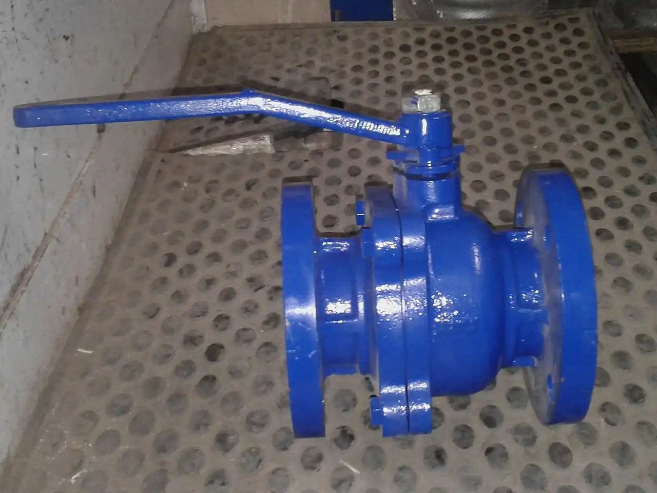
Every ball valve specification quietly answers one question: what holds the ball in place? A floating ball is clamped between seats and pushed into the downstream seat by line pressure; a trunnion-mounted ball is anchored on bearings, and the seats press toward the ball instead. Those two answers set the valve's size range, pressure envelope, torque curve, and cavity relief options, which is why the choice comes from the line data, not the price list.
The decision appears in every plant. An NPS 2 Class 300 water isolation point is commodity territory where a floating valve wins on price, stock, and simplicity. An NPS 24 Class 600 pipeline block valve must cycle against full line differential, vent its body cavity, pass a pig, and accept a spring-return actuator: that is trunnion country. Between those poles sits the grey zone, roughly NPS 4 to 8 at Class 600, where both constructions can be quoted and the torque sheet, not the brochure, decides.
This page treats the choice as an engineering decision with numbers attached: seat load physics and torque growth with differential pressure, pressure class and size boundaries, seat material envelopes, the standards that give the datasheet meaning, and a field practice chapter on actuator sizing, installation, and maintenance intervals.
This guide is aimed at industrial purchasing and design engineers. It covers 6 chapters from ball support mechanics and torque behavior through classes, constructions, seats, and standards to a crossover rule by NPS and ASME class plus field practice, with 7 FAQs. Standards referenced include API 6D, API 608, ASME B16.34, ASME B16.10, ASME B16.5, API 607, API 6FA, API 598, ISO 5208, ISO 15848-1, and ISO 5211.
Chapter 1 / 06
Two Ways to Support a Ball
A ball valve is a quarter-turn isolation device: a bored sphere rotates 90 degrees between an open position that presents a full or reduced bore to the line and a closed position where two seat rings seal against the ball. Set against the alternatives, its case is tight shutoff with soft seats, fast operation, and a compact face-to-face. A gate valve needs many turns and full stem travel to close but stays economical in very large, low-drop isolation; a globe valve trades pressure drop for throttling authority a ball does not have; a butterfly valve undercuts everything on price and footprint above NPS 12 but seals less tightly; a check valve is not an isolation device at all, since it responds to backflow rather than to operator intent. Specifiers reach for a ball valve when the duty is open or closed, leakage class matters, and quarter-turn speed or automation is wanted.
In the floating design the ball hangs on the stem and the two seats. Upstream pressure shifts the ball downstream, and the downstream seat does the sealing. The higher the pressure and the bigger the bore, the harder the ball is driven into that seat. The construction is simple: no trunnions, no bearings, no seat springs, which is exactly why it is cheap.
In the trunnion design the ball rides on upper and lower journals running in bearings fixed to the body, so line pressure cannot move it. Each seat is pushed toward the ball by springs and by line pressure acting behind the seat rings. Sealing force is engineered and bounded instead of growing with differential pressure, and the pressure load path runs through bearings sized for it.
The distinction looks like a drafting detail, yet four datasheet lines hang on it: the pressure class and bore the valve can carry, the operating torque curve and therefore the actuator or gear operator, the seat materials that survive the loading, and the cavity behavior when trapped liquid warms in a closed valve. Each of those lines carries a cost and a lead time, so the decision belongs in the specification stage, sourced from line data: fluid state, maximum differential pressure, temperature, size, and class.
Neither design is universally better, and the market reflects it. Floating dominates the small-bore commodity range from NPS 1/2 to about NPS 6: utility isolation, instrument manifolds, skid work, hardware catalogs. Trunnion dominates pipeline and high-class isolation, where a floating ball would be inoperable or leak: API 6D pipeline block valves, HIPPS shut-off duty, and large-bore process isolation. This chapter pair explains where each support style stops working, and the chapters after it put numbers on the boundary.
Chapter 2 / 06
Seat Load Physics and Torque Behavior
In a floating ball valve the ball is suspended between two seat rings with no separate bearing. Upstream pressure acts on the projected ball area bounded by the seat seal diameter and shifts the ball downstream, so the downstream seat carries nearly the whole unbalanced force. That force grows linearly with differential pressure: F is approximately dP x A, where A is the seat-enclosed area. For an NPS 6 full-bore valve the seat-enclosed area is about 0.02 m², so 10 bar of differential pressure loads the downstream seat with about 20 kN, and 100 bar, the full Class 600 rating, loads it with about 200 kN, the weight of roughly 20 tonnes pressing on a pair of polymer rings.
Seat friction converts that load into stem torque. Breakaway torque is approximately T0 plus the product of friction coefficient, seat load, and effective friction radius, where the friction coefficient for PTFE against steel runs about 0.05 to 0.15 and rises with temperature and wear. Because seat load is linear in differential pressure, floating ball valve torque is linear in differential pressure: every additional bar of differential adds a fixed increment of breakaway torque. A lever handle that opens the valve comfortably against 10 bar can be unusable against 50 bar, and gear operators or actuators must be sized for the maximum credible differential, not the nameplate class at zero flow.
The second limit is seat stress. Soft seat materials have compressive limits; PTFE grades sit roughly between 10 and 25 MPa depending on filler content and temperature, and the limit falls as the valve warms. At small bores the seat contact area carries the load with margin. At NPS 8 and above in Class 600 service the contact stress approaches the extrusion limit of unfilled PTFE, which is why reinforced seats, higher-performance polymers, or a trunnion design take over. Extruded seats announce themselves later as rising leakage and rising torque.
In a trunnion-mounted ball valve the ball is pinned to the body through trunnion journals running in bearings. Line pressure cannot shift the ball; the pressure load path runs ball to trunnion to body instead of ball to seat. Each seat is pushed toward the ball by a spring stack, giving shutoff at low or zero differential, and by line pressure acting on the back of the seat ring, which behaves like a piston and energizes the seal as pressure rises. Sealing force is therefore engineered: spring preload sets the floor, and the pressure-energized increment acts on the small seat ring annulus rather than the full bore area, so it stays bounded and nearly independent of bore.
The torque consequence is the headline difference buyers see on datasheets. Manufacturers quote 30 to 40% lower operating torque for trunnion at high differential, and more importantly the torque is nearly flat across the pressure range, which makes actuator sizing deterministic instead of iterative. The table below shows the shape of the curves with illustrative catalog-style figures for an NPS 6 Class 600 valve with PTFE seats; always request the manufacturer torque sheet for the exact size, class, seat material, and temperature.
Attribute, NPS 6 Class 600 example
Floating Ball
Trunnion Ball
Break torque at 10 bar differential
approx 210 Nm
approx 155 Nm
Break torque at 40 bar differential
approx 660 Nm
approx 165 Nm
Break torque at 100 bar differential
approx 1550 Nm
approx 190 Nm
Torque growth law
Linear in differential pressure
Near flat, spring preload dominates
Seat load at 100 bar, full bore
approx 200 kN on downstream seat
approx 5 to 15 kN spring force plus bounded piston load
Cavity overpressure behavior
Ball lifts upstream seat, uncontrolled
Self-relieving seats vent to the low side
Trunnion seat architecture also manages the body cavity. Self-relieving (upstream) seats act as relief valves: when trapped liquid in the closed cavity expands and cavity pressure exceeds upstream pressure by a set margin, the upstream seat lifts briefly and vents the excess back into the line. Double piston effect seats invert the logic, pressure-energizing from both sides for tighter sealing, but they no longer self-relieve, so a valve with double piston effect seats on both sides needs an external cavity relief valve. Floating valves rely on the ball lifting off the upstream seat, which relieves but is uncontrolled and can unload the sealing seat at high differential.
What to do with this chapter: for any actuated valve, demand the breakaway torque at maximum differential pressure, at maximum service temperature, and with the actual seat material quoted. Torque data taken at ambient temperature with standard seats can undersize an actuator by half on hot service, and torque data for the wrong seat polymer undersizes it further. Running torque typically sits at 50 to 70% of breakaway; ask for break, run, and end positions separately.
Chapter 3 / 06
Classes, Constructions, and Duty Boundaries
The practical envelope follows directly from chapter 2. Floating ball valves are offered from NPS 1/2 through about NPS 12, and they are workable up to about Class 600 (PN100), but the two limits trade against each other. At Class 150 and 300, sizes to about NPS 8 remain comfortable and NPS 10 to 12 are quotable with reinforced seats. At Class 600, floating is credible to about NPS 4, and above Class 600 most catalogs drop floating entirely because seat loading and torque make it impractical. API 608 governs floating ball valve design with flanged or butt-weld ends through Class 600.
Trunnion designs exist in small bores as specialty items but become the standard construction from about NPS 2 upward, run through Class 2500 (PN420), and reach NPS 60 and beyond in pipeline service. API 6D is the pipeline valve specification most large trunnion valves are built to: it addresses bore (full or reduced), cavity relief provisions, double block and bleed capability, and options for buried or subsea service. Where a floating valve needs the line to be gentle with it, a trunnion valve only needs the line data to be honest.
Body construction splits along serviceability lines. For floating valves, one-piece bodies are investment cast with the ball assembled through an end; they are the cheapest, cannot be serviced, and dominate below NPS 2. Two-piece bolted bodies carry the NPS 2 to 6 commodity range. Three-piece bodies bolt the center segment between two end connectors, so seats and seals can be replaced inline without breaking the flange joints; they are the default for small process stations where downtime matters.
Trunnion bodies come in three architectures. Side-entry split bodies unbolt to expose ball and seats, and they are the standard for NPS 6 to 60 process and pipeline valves. Top-entry designs lift a bonnet to service internals with the valve still in the line, preferred where removal is expensive. Fully welded bodies eliminate the body joint leak path entirely and dominate buried and subsea pipelines; the trade-off is that nothing is serviceable without cutting the valve out.
Double block and bleed is a construction consequence of the seat architecture. Per API 6D, a trunnion valve with two self-relieving seats gives single-body double block and bleed: both seats seal independently from either direction, and a bleed port between them vents the cavity or verifies zero leakage. One valve then replaces two sequential valves and a spool piece. Floating valves are sometimes marketed as double block and bleed because they have two seats, but with the ball free to move only one seat carries load at a time, so the claim does not survive a seat test. Valves with two closure members in one body, the true double block and bleed valve, and double isolation and bleed variants with double piston effect seats, are their own product family under API 6D definitions.
Fire-tested design and fugitive emission control are qualifications either construction can carry, but they are routine asks on trunnion specifications. Fire tests API 607 and API 6FA, harmonized with ISO 10497, expose the valve to a hydrocarbon flame for 30 minutes and then require acceptable closure and external leakage with the soft seats burned away, through metal backup sealing. Fugitive emission qualification per ISO 15848-1 grades stem sealing systems by tightness and endurance class, with graphite-based systems carrying the hot end. Buy both as certificates, not adjectives: the API 607 test report number and the ISO 15848-1 class belong on the datasheet, with the certificate on file.
Knowing where the ball valve stops is part of the same boundary map. Very large, low-pressure isolation favors a butterfly valve on cost and weight. Low-pressure slurry isolation is often better served by a knife gate valve, whose blade shears settled solids instead of trapping them in a ball cavity. High pressure drop throttling is a control valve job, and fine metering at small flow is needle valve territory. For pump discharge, the ball valve handles isolation while a swing check valve or other check valve family member handles reverse flow.
Attribute
Floating Ball
Trunnion Ball
Typical size range
NPS 1/2 to 12 (DN 15 to 300)
NPS 2 to 60 and above (DN 50 to 1500+)
Practical class ceiling
Class 600 (PN100), size-limited
Class 2500 (PN420)
Governing standards
API 608, ASME B16.34
API 6D, ASME B16.34
Body styles
One-piece, two-piece, three-piece
Side entry, top entry, fully welded
Seat service
Three-piece: inline seat swap
Side or top entry service, sealant injection on metal seats
Double block and bleed
Not by design
Two self-relieving seats plus bleed, per API 6D
Cavity relief
Uncontrolled ball lift
Self-relieving or double piston effect seats, external relief where both seats are DPE
Relative cost, same size and class
1x
approx 2 to 4x at NPS 4, widening with bore and class
Chapter 4 / 06
Seats, Seals, and Key Specification Parameters
Seat material is the second selection axis, decided after the support design. The seat has to survive temperature, differential pressure, and the medium itself, in roughly descending order of temperature capability. The envelope below is the catalog consensus; the binding constraint inside each envelope is the pressure-temperature derating of both the seat polymer and the body rating, which is why a seat quoted to 230 C still needs the class chart checked at operating temperature.
Seat material
Approx temperature envelope
Where it wins
Watch-outs
Virgin PTFE
approx -50 to +200 C
Clean liquids and gases, Class 150 to 300
Cold flow and extrusion at high differential
Reinforced PTFE, 15 to 25% glass
approx -50 to +230 C, class-derated
Class 300 to 600 general process duty
Higher torque, abrasive wear of filler
PEEK
approx -50 to +250 C
Class 600 to 2500, high differential, hot hydrocarbons
Higher seat loads at moderate temperature, oil service
Water absorption, hard temperature ceiling
Metal seat with WC or CrC hardfacing
approx -196 to +400 C and above
Steam, slurries, abrasive slugs
Higher leakage class, sealant injection, cost
Sealing does not end at the seats. Stem sealing controls fugitive emissions: an elastomer O-ring (NBR, FKM, or EPDM, selected by fluid and temperature) gives the tightest cold seal, graphite packing survives fire exposure, and fire-safe stem designs combine both, with the O-ring intended to burn out and the graphite taking over. Body joint seals on split-body valves use a spiral wound or kammprofile gasket sized to the body bolting. End connections seal through the piping: a raised face flange takes a compressed fiber or spiral wound gasket matched to its class, ring joint flanges at Class 900 and above take metal ring gaskets, and welded ends move the seal into the pipe weld itself, which is why buried pipeline valves are welded, not flanged.
The datasheet decode follows. Each row is a number to demand, with the standard that gives it meaning; a datasheet line without its standard is a number nobody can test against.
Datasheet line
What it encodes
Standard and how to read it
Pressure class
Body pressure-temperature envelope
ASME B16.34; check the rating at operating temperature, not ambient, since Class 600 carbon steel at 340 C holds roughly half its ambient rating
Face-to-face dimension
Piping envelope
ASME B16.10; long versus short pattern changes pipe spools and supports
End flange
Bolt pattern and gasket surface
ASME B16.5 through NPS 24; raised face standard, ring joint at Class 900 and above
Wall thickness
Minimum body wall
API 6D or API 608 route depending on which valve specification the order runs under
Seat leakage rate
Shutoff quality
API 598: no visible leakage for resilient seats at test; ISO 5208 Rate A for soft seats, Rate B or C typical for metal seats
Fire type test
Post-fire sealing capability
API 607 or API 6FA, harmonized with ISO 10497; record the test report number
Fugitive emission class
Stem sealing tightness and endurance
ISO 15848-1; state tightness class and endurance class on the datasheet
Actuator mounting
Pad, bolt circle, drive
ISO 5211 flange and drive dimensions; size the drive bush to the stem
Sour service
Material hardness limits
NACE MR0175 / ISO 15156 when H2S is present
Two more lines separate careful suppliers from the rest. An antistatic device, meaning ball to stem to body electrical continuity, is standard practice on hydrocarbon service and required by many operator specifications; verify continuity on receipt with a multimeter, since a PTFE-seated ball is otherwise electrically isolated. A cavity relief statement names which seats are self-relieving, which are double piston effect, and what relief margin applies; a datasheet silent on cavity relief for a liquid service is a red flag, not a saving, because trapped liquid expansion is a certainty the moment the sun finds a closed valve.
Chapter 5 / 06
Selection Decision Factors and Application Mapping
The decision sequence below is ordered so that each step eliminates the most options at the least cost. Run it in order and the construction choice usually falls out before step 4; run it out of order and you will re-specify actuators twice.
Size and class first. Inside the floating envelope (about NPS 8 at Class 150 to 300, NPS 4 at Class 600, NPS 2 at Class 900 and above), floating is the economical default. Outside it, trunnion is not a preference, it is the only quoteable construction.
Differential pressure and torque. Establish the maximum credible differential, not the design pressure: a downstream depressurization case can put full upstream pressure across a closed valve. Check breakaway torque at that differential; if the operator becomes oversized, the torque sheet is unavailable, or hot-service data is missing, move to trunnion.
Cavity and DBB needs. Liquid-full lines exposed to heat, or isolation-plus-vent duty, need self-relieving seats and a bleed port, which in practice means API 6D trunnion. Confirm whether the application needs field double block and bleed or the API 6D single-valve definition.
Media and seats. Clean utility service suits soft-seat floating valves. Abrasive, slugging, or hot service pushes to trunnion with reinforced or metal seats, because the seat then no longer carries the full bore load.
Fire, fugitive, sour qualifications. Flammable service adds API 607 or API 6FA; emission-controlled sites add ISO 15848-1; wet H2S adds NACE MR0175 / ISO 15156. Both constructions can qualify, so these constraints set the package, not the choice.
Actuation. Manual levers work to about 100 Nm of break torque as a rough ergonomic limit; beyond that, gear operators or actuators. An electric actuator suits remote, low-cycle sites; a pneumatic actuator with spring return suits high-cycle and fail-close ESD duty. Both interface through ISO 5211 mounts.
Economics and service. Weigh seat kit pricing, inline serviceability (three-piece floating), sealant injection provision (trunnion metal seats), spares strategy, and lead time. A valve whose seats can be swapped in an afternoon beats a cheaper one that must be cut out.
Application mapping turns the same logic into a lookup table. These pairings are where the two constructions actually live in industrial practice:
Application
Recommended construction
Why
Pipeline ESD valve, NPS 16 to 48
Trunnion, API 6D, full bore, DBB, spring-return actuator
Must close against full line differential, pass pigs, vent cavity, and fail closed without power
HIPPS shut-off valve
Trunnion, Class 600 to 2500
Safety-instrumented duty needs repeatable fast closure, commonly about 2 seconds or less, against full differential, with partial stroke testing
Process isolation, NPS 2 to 4, Class 150 to 300
Floating, three-piece body
Commodity price with inline seat service
Instrument isolation, NPS 1/2 to 1
Floating small bore, or a needle valve where metering is needed
No load case beyond class; double block and bleed manifolds save fittings
Slurries and slugging service
Trunnion with metal seats, or a knife gate valve at low pressure
Ball cavity traps solids; floating soft seats get torn by the full pressure load
Dry gas, emission-controlled
Either, with ISO 15848-1 stem sealing and matched seats
Tightness comes from the seat and stem package, not ball support, once dP is moderate
Pump discharge isolation plus backflow protection
Ball valve plus swing check valve
The ball isolates on demand; the check handles reverse flow continuously
Cost tracks part count. A commodity NPS 2 Class 150 carbon steel floating valve is a catalog item in the low tens of dollars; the same size in Class 600 floating roughly triples; a trunnion NPS 2 Class 600 starts in the hundreds of dollars; and an API 6D NPS 24 Class 600 trunnion with dual actuators runs to five figures or more. The premium buys operability at bore and class that floating cannot deliver, and it recurs in maintenance: floating seat kits are cheap and stocked everywhere, while trunnion spares, meaning seats, springs, bearings, and injection fittings, should be bought with the valve because they are not commodity items.
What to write in the RFQ, as a checklist:
Fluid state and composition, including solids loading and H2S partial pressure
Design pressure and maximum differential pressure across the closed valve, including upset cases
Temperature range and expected thermal cycles
Seat material and required leakage class per API 598 or ISO 5208
Fire test requirement, API 607 or API 6FA, with report reference
Fugitive emission class per ISO 15848-1
Bore requirement, full or reduced, and pigging needs
End connection, face-to-face per ASME B16.10, flange standard per ASME B16.5
Actuation, fail action, and ISO 5211 mounting interface
Cavity relief statement and body construction (one, two, three-piece, side entry, top entry, welded)
Chapter 6 / 06
Field Practice: Actuators, Installation, and Maintenance
Actuator sizing starts at the break. Request the unseating or breakaway torque at maximum differential pressure and maximum service temperature for the actual seat material quoted, then apply a safety margin of 25 to 30% on top, and check run and end torque separately, since running torque typically sits at 50 to 70% of breakaway. For a spring-return pneumatic actuator, size the air side at the minimum credible supply pressure, a plant header at 6 bar on a bad day rather than the 7 bar nameplate, and size the spring to complete the fail stroke at the required torque including the margin. For an electric actuator, verify the torque curve at the actual supply voltage and frequency, because undervoltage derates torque, and check the duty cycle rating against the expected operation count; a valve that strokes four times an hour on a valve designed for four a day will cook its motor.
Choose the power source by duty and failure requirement. A pneumatic actuator with spring return is the default for emergency shutdown, HIPPS, and blowdown duty: fast, tolerant of high cycle rates, and fail-safe without controls, at the cost of instrument air quality and supply. An electric actuator suits remote sites, infrequent operation, and precise partial stroking, with fail action achievable only through battery or capacitor backup, which must be specified and tested. Both mount through ISO 5211 pads; verify the drive bush, key or square dimensions, and the locking device that holds the manual override.
Do not convert an isolation ball valve into a control valve by bolting a positioner to it. The positioner will stroke modulating angles without complaint, but the ball is not shaped for pressure recovery: partially open at high differential, the flow jets through the partial bore at high local velocity, and the resulting seat cutting, wire draw, and cavitation damage follow quickly. A chewed seat no longer seals when isolation is actually needed, which is how a throttled-open bypass becomes a plant trip. Characterized ball trims exist for modest modulating duty at moderate pressure drop, but sustained pressure-drop regulation belongs to a globe-pattern control valve with engineered anti-cavitation trim. Keep ball valves fully open or fully closed; if the line needs something in between continuously, the correct line item is a control valve, and if the process needs fine small-flow metering, it is a needle valve.
Installation errors sink both constructions equally. Flange bolts go in a cross pattern in at least three passes, roughly 30%, 70%, and 100% of target torque, with a calibrated wrench, so the gasket seats evenly; uneven bolt torque on a floating valve distorts the body enough to pinch the ball, and on a trunnion valve it bends the seat carrier. Match the gasket to the flange class and surface finish, and never use a heavier gasket than the class allows to chase a leak. The piping must arrive at the valve strain-free: pipe loads bend bodies, cock seats, and jam balls, so support the pipe independently and support NPS 8 and larger valves on their own; never take pipe alignment allowance out of the valve bolts, and never let the valve carry the weight of an unsupported riser.
Seat damage from partially open operation deserves its own paragraph because it is the most common self-inflicted wound. A ball valve used for prolonged throttling at high differential wears its downstream seat edge into a step; torque rises, leakage class degrades from Rate A toward Rate C, and the damage is invisible until the first real isolation demand. If turndown is unavoidable temporarily, schedule it, log it, and inspect the seat afterward. Verify cavity relief behavior at commissioning rather than at the first sunny day: with the valve closed and the bleed open, pressurize upstream and confirm the self-relieving seat reseats cleanly; for double piston effect seats, confirm the installed external relief valve and its set pressure, and record the relief direction in the commissioning file.
Testing and maintenance intervals close the loop. Factory testing runs per API 598 or the ISO 5208 rate called out on the datasheet; hold the supplier to the certificate. On site, seat integrity is checked by a low-pressure closure test at each shutdown, and stem fugitive emissions can be spot-checked with a portable detector against the ISO 15848-1 acceptance basis. ESD and HIPPS valves get partial stroke tests every 3 to 6 months and full function tests at turnarounds, typically every 12 to 24 months, with results feeding the safety instrumented system proof test record. Trunnion valves with metal seats may need sealant injection, but only when leakage indicates it; injection on a schedule gums the cavity. Floating three-piece valves get seat kit replacement when closure leakage exceeds the specified rate, which is a one-afternoon job if the kits are on the shelf.
The economics of maintenance favor planning over reaction. Buy seat kits with the valve, one kit per three valves for a common size is a working rule; buy trunnion spares kits with the valve because seat rings and bearings are matched parts, not catalog items; and standardize body styles per station so one training course and one torque table cover the fleet. A station that mixes one-piece floating, three-piece floating, and side-entry trunnion valves in the same size pays for that variety in spare parts, procedures, and mistakes at 2 am.
The summary rule, one line for the specification meeting: small bore and moderate class, floating; large bore, high class, dirty media, or cavity-relief duty, trunnion; anything actuated, decide on the torque sheet at maximum differential, not on the brochure.
FAQ
At what size and class should I switch from floating to trunnion?
Supplier working rule: floating to about NPS 8 at Class 150 to 300, NPS 4 at Class 600, NPS 2 at Class 900 and above. Below those points floating is simpler and cheaper; above them seat loading and torque grow with bore and pressure, and only trunnion keeps both predictable. Treat the rule as a screen, then confirm against the pressure-temperature chart and the torque sheet for your seat material and maximum differential.
Why does operating torque grow with pressure on a floating ball valve?
The ball is not fixed: line pressure pushes it downstream against the seat, so seating force and friction torque rise linearly with differential pressure and bore area, until a lever or compact actuator cannot cope. A trunnion valve moves that load into bearings, which is why manufacturers quote 30 to 40% lower operating torque that stays nearly flat as pressure rises.
What is double block and bleed on a trunnion valve?
A trunnion valve with two self-relieving seats seals from either side and isolates the cavity: both seats block while a bleed port vents or verifies zero leakage, per API 6D. One valve then does isolation and venting that would otherwise need two valves and a spool. Floating valves give no such guarantee, since only one seat is loaded at a time.
Do I need cavity pressure relief for liquid service?
Yes, whenever the closed cavity can warm while isolated, such as sunlight on a liquid-full line: trapped liquid expansion can unseat a floating ball or overload soft seats. API 6D trunnion valves vent excess cavity pressure through self-relieving seats; if both seats are double piston effect, an external cavity relief valve is required. Confirm relief direction and setting with the manufacturer and verify at commissioning.
When is fire-safe certification required?
Flammable services normally require qualification to API 607 or API 6FA, harmonized with ISO 10497, which verifies that a soft-seat valve still seals after the seats burn out, through metal-to-metal backup. Both designs can qualify; it is a seat and seal package question, not a ball support question. Specify the test report number with the valve and keep the certificate on file.
Which design suits slurries and dirty media?
Prefer trunnion with metal or coated seats. In a floating valve, particles embed in or tear the soft seat that carries the full pressure load, and seating force cannot be controlled. Trunnion valves with metal seats and hardfacing keep sealing in abrasive media; add upstream strainers where the process allows, and consider a knife gate valve instead when pressure is low and solids settle.
Which is cheaper to buy and maintain?
Floating, by a wide margin at small sizes: commodity one-, two-, and three-piece bodies with cheap seat kits, and a three-piece body services seats inline. A trunnion valve costs more because of trunnion bearings, seat springs, and body complexity; at large bore or high class that premium buys operability floating cannot deliver. Buy trunnion spares kits with the valve, since they are matched parts rather than catalog items.